



Designing Battery Packs for Peak Power and Pulse Loads By Anton Beck, Battery Product Manager Epec Engineered Technologies
Battery pack design is often discussed in terms of capacity, runtime, voltage, and chemistry, but many applications are driven just as much by peak power and pulse load requirements. A battery pack may have enough stored energy to support the expected runtime but still fail in the field if it cannot safely deliver short bursts of high current. This is common in products with motors, pumps, transmitters, heaters, actuators, medical devices, military electronics, robotics, and other systems that demand power in short, intense intervals.
Capacity Alone Does Not Define Peak Power
Designing for peak power is not simply a matter of selecting the highest-capacity cell. Capacity, usually measured in amp-hours, tells us how much energy the cell can store and deliver over time under defined conditions. Peak power is more closely tied to the cell’s discharge capability, internal resistance, temperature behavior, chemistry, construction, protection circuitry, interconnect design, and thermal path.
A high-capacity cell may actually have a lower maximum discharge rating than a lower-capacity power cell. For this reason, battery pack design must begin with the actual load profile, not just the desired runtime.
Understanding Pulse Load Requirements
A peak power event is typically the highest short-duration power demand the system will place on the battery. A pulse load is a repeated or temporary demand where current rises sharply for a defined period before returning to a lower steady-state level. The difference matters because a battery pack that can survive one short pulse may not be able to support repeated pulses without voltage sag (Figure 1), heat buildup, accelerated aging, or protection circuit shutdown.
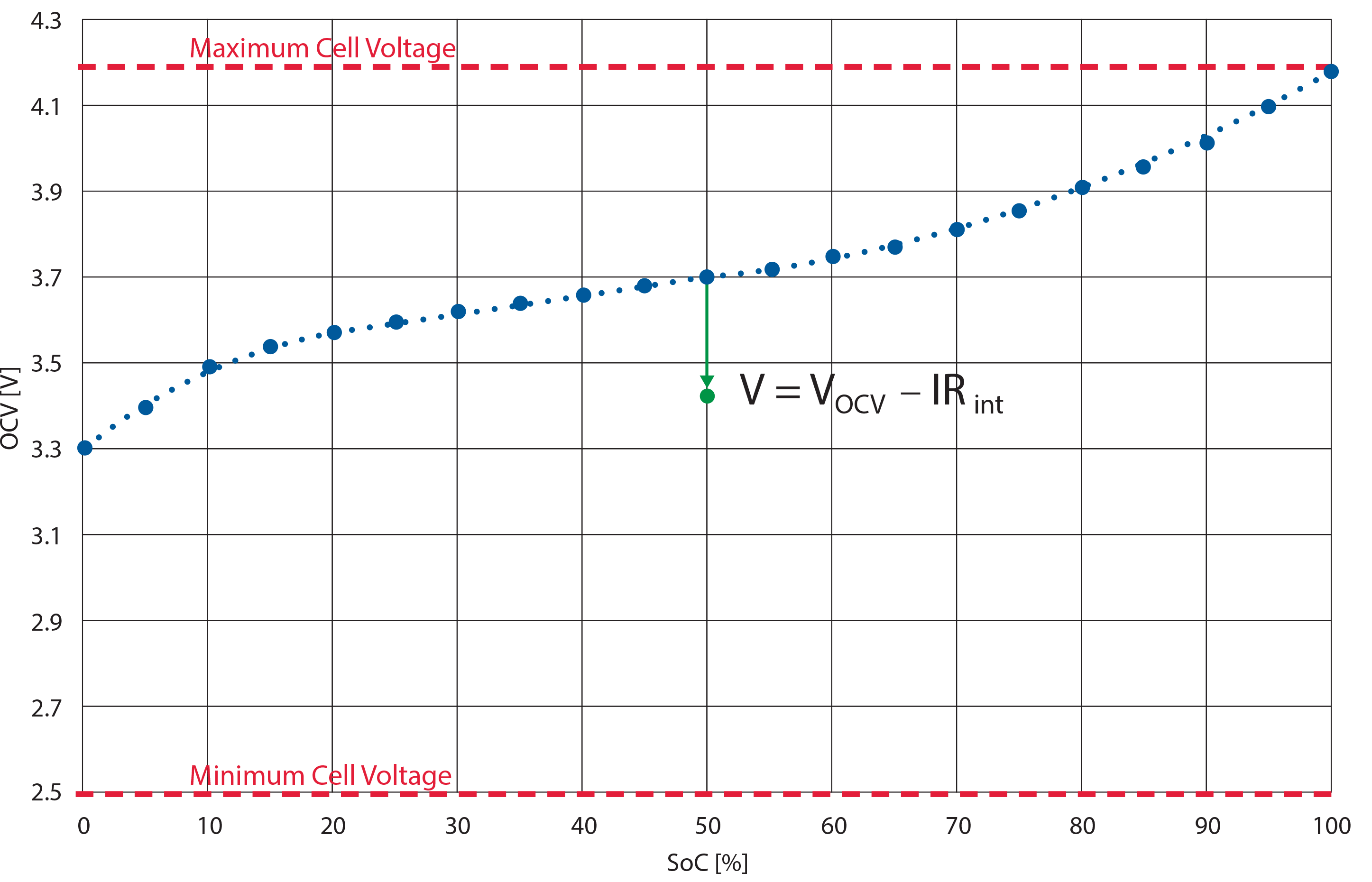 Figure 1: Cell voltage sag under load caused by internal resistance.
Engineers need to know the pulse current, pulse duration, rest time between pulses, number of pulses, operating temperature range, cutoff voltage, and whether the equipment can tolerate voltage drop during the event.
Cell Selection Comes Before Electronic Settings
Peak power is influenced by both cell selection and electronic settings, but the cell must come first. The battery management system (BMS) can enforce current limits, voltage limits, temperature limits, and fault responses, but it cannot make a cell safely deliver more current than it is designed to provide. If the cell chemistry and construction cannot support the load, changing the BMS settings only increases risk. A properly designed pack uses cells with the correct continuous and pulse discharge ratings, then pairs them with a BMS and protection circuit that match the intended operating envelope.
The Role of the BMS in Peak Power Control
The BMS plays an important role (Figure 2) in managing peak power and pulse loads, but peak power is not only a BMS function. The BMS monitors and controls conditions such as overcurrent, short circuit, overvoltage, undervoltage, overtemperature, and cell balancing. In some designs, it may also include programmable discharge limits or communication with the host device.
However, the ability to handle pulse loads also depends on the cell arrangement, nickel or copper bus design, weld quality, connector ratings, wire gauge, PCB copper weight, fuse selection, current sense components, and heat dissipation. A weak point anywhere in the current path can limit the pack, even if the cells and BMS are correctly specified.
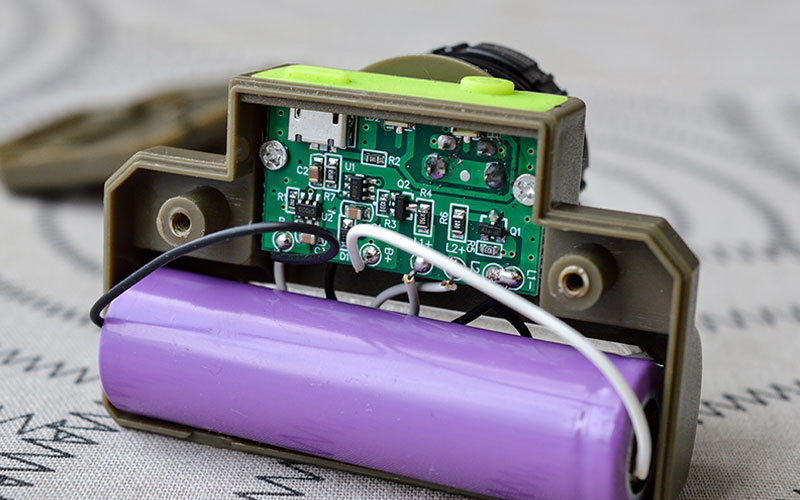 Figure 1: Battery management system circuitry connected to a cylindrical lithium-ion cell within an assembled battery pack.
Chemistry Impacts the Design Approach
These design considerations are not limited to one chemistry. Lithium-ion, lithium iron phosphate, nickel metal hydride, lead acid, and primary lithium chemistries can all have peak power or pulse load requirements. The way each chemistry responds is different. Lithium-ion power cells may support high discharge rates but require careful thermal and protection management. Lithium iron phosphate cells often offer strong thermal stability and cycle life, but the design still needs to account for voltage profile and current limits.
Primary lithium chemistries may be used in remote or military applications where long shelf life and pulse capability are important. Still, pulse performance can be highly dependent on cell type and temperature. The chemistry does not remove the engineering requirement. It changes the design approach.
Why Applications Require Pulse Load Design
There are several reasons to design specifically for pulse loads. Some devices only need high power for a fraction of their operating cycle, such as motor startup, wireless transmission, valve actuation, heating ramp-up, or emergency signaling. Designing the battery pack only for average current can lead to field failures because the average load hides the true stress placed on the cells and electronics. Pulse load design helps ensure the pack can support real system behavior, not just a simplified current draw calculation.
How Pulse Load Design Can Support Battery Life
Pulse load design can help extend battery life when handled correctly. A pack that is sized appropriately for pulse current will experience less voltage sag and less thermal stress than a pack operating near or beyond its limits. Lower stress during high-current events can reduce cell heating, avoid nuisance protection trips, and help preserve usable capacity over time.
This does not mean pulse loads are automatically good for battery life. It means that engineering the pack around the pulse profile can prevent the damage caused by undersized cells, poor current paths, or overly aggressive protection settings.
When Peak Power Can Reduce Battery Life
Peak power demands can reduce battery life if they are frequent, excessive, or poorly managed. High-current events increase internal heating, and heat is one of the major contributors to battery aging. Repeated high discharge rates can also increase cell imbalance, reduce available capacity, and accelerate impedance growth.
If the design repeatedly pulls cells down near cutoff voltage during peak events, the user may see shorter runtime, earlier shutdowns, and faster performance decline. This is especially important in applications where the pack operates at elevated ambient temperatures or inside sealed enclosures with limited cooling.
Defining the Battery Pack Load Profile
A sound design process starts with defining the load profile in detail. Engineers should document continuous current, peak current, pulse duration, duty cycle, startup current, cutoff requirements, temperature range, and expected life. From there, the cell is selected based on both energy and power capability. The series and parallel configuration must support voltage, runtime, and current sharing.
The BMS is then selected or designed to protect the pack without interfering with normal system operation. Mechanical packaging, interconnects, wiring, connectors, and thermal pathways are verified against the same pulse and peak conditions.
Validating Peak Power and Pulse Performance
Testing is critical because datasheets provide starting points, not final proof of performance. Real pack behavior depends on the completed assembly. Validation should include pulse discharge testing, continuous discharge testing, voltage sag measurement, thermal rise, low-temperature performance, protection circuit response, and cycle testing under a representative load profile. When possible, testing should reflect the actual host device rather than a purely theoretical load.
Designing Around Real Application Demands
Designing battery packs for peak power and pulse loads requires balancing capacity, power delivery, safety, thermal performance, and service life. The highest-capacity cell is not always the correct cell, and the BMS alone cannot compensate for an undersized electrochemical or mechanical design. A reliable pack is built around the real behavior of the application, with the cells, electronics, interconnects, and enclosure working together to support both steady-state operation and short-duration high-power demand.
For OEMs, the key takeaway is simple: runtime calculations are only part of the battery pack design process. If the product has startup surges, repeated bursts, transmit cycles, heating events, or motor loads, those conditions must be engineered into the pack from the beginning. Proper peak power and pulse load design helps improve reliability, reduce premature shutdowns, and support long-term battery performance in the field.
Summary
A successful design starts with an accurate load profile that defines continuous current, peak current, pulse duration, duty cycle, operating temperature, and voltage limits.
Selecting the correct cells and validating the completed pack under realistic operating conditions can reduce voltage sag, overheating, premature shutdowns, and accelerated aging.
By designing around the actual demands of the application, OEMs can improve battery pack reliability, safety, and long-term performance.
Need Help Designing a Battery Pack for Peak Power Applications?
Whether your application requires high startup currents, repeated pulse loads, or continuous high-power operation, Epec's engineering team can help you develop a battery pack designed around your actual operating conditions. From cell selection and BMS design to thermal management, validation testing, and production, we work closely with OEMs to deliver reliable battery pack solutions that meet demanding performance, safety, and lifecycle requirements. Contact our team to discuss your application or request a quote for your next custom battery pack project.
Request a Quote Request Design Support