



How to Calculate and Select Watt Density for Flexible Heaters By Steven J. Goodman, Product Manager Team Lead Epec Engineered Technologies
Watt density describes how much electrical power a flexible heater generates per unit of effective heated area. It directly influences warm-up performance and the thermal demands placed on the heater’s materials. For a given heated area, higher watt density means higher total heater power. Selecting too high a watt density can cause premature heater burnout or, depending on supply voltage and heater resistance, draw excessive current from the system. Engineers must evaluate how efficiently heat moves from the resistance element into the application before establishing the required power.
A heater bonded to an aluminum plate can operate very differently from an identical heater attached to plastic or suspended in air. The electrical input may be the same, but the resulting element temperature depends on the complete thermal path.
How Is Watt Density Calculated?
Watt density is calculated by dividing total heater power by effective heated area:
Watt Density (W/in²) = Total Power (W) ÷ Heated Area (in²)
Watt density is expressed in watts per square inch (W/in²), total power in watts (W), and heated area in square inches (in²).
For example, a 100-watt heater with 16 square inches of effective heated area has a watt density of 6.25 W/in².
The important detail is how the effective heated area is defined. Unheated borders, cutouts, and lead termination regions can reduce the area available for heat generation. Using the heater’s overall dimensions without accounting for these features can understate its actual average watt density. Confirm the area convention with the heater manufacturer before comparing designs or published ratings.
Determine the Application’s Heating Requirements
Start by defining the initial temperature, target temperature, allowable warm-up time, and operating environment. Include the mass and thermal properties of everything the heater must bring to temperature, including mounting plates, housings, fixtures, and process materials.
A heavier assembly generally requires more energy to achieve the same temperature rise. Faster warm-up requires delivering that energy over a shorter period, which increases the required power (Figure 1).
Heat losses must also be considered. Airflow removes heat through convection, exposed surfaces exchange heat through radiation, and brackets or fasteners conduct heat into surrounding structures. These losses change as the assembly warms, so room-temperature measurements alone will not establish the power required at the operating setpoint.
Distinguish warm-up power from holding power. A heater sized to reach temperature quickly may require substantially less average power once the assembly reaches its setpoint. The control system must accommodate both conditions.
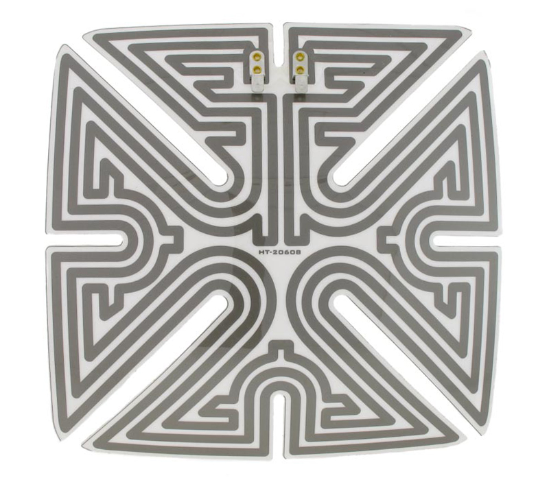 Figure 1: Etched foil pattern and trace width directly correlate with heater power.
Evaluate the Thermal Path
The resistance element normally operates hotter than the surface being heated. Heat must travel through the heater’s dielectric layers, bonding materials, and mounting interface before reaching the application. Adding silicone foam insulation to the opposite side of the heater can reduce heat loss and help direct heat toward the targeted region (Figure 2).
Each layer adds thermal resistance. Increasing adhesive thickness or selecting a material with lower thermal conductivity increases the temperature difference between the element and the heated surface.
Surface contact is equally important. Wrinkles, trapped air, contamination, or incomplete bonding can interrupt heat transfer. These defects may produce localized overheating even when the heater’s average watt density is within its specified limit.
Evaluate the actual mounting stack, including adhesive, surface finish, curvature, and attachment method. A heater qualified on a flat metal surface should not automatically be assigned the same operating limits when installed on a different substrate.
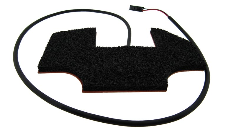 Figure 2: Adding silicone foams to a heater can help direct heat towards a targeted region.
Select Materials Based on Element Temperature
Polyimide and silicone rubber heaters should be evaluated as complete constructions. Encapsulation of temperature capability alone does not establish allowable watt density. Internal adhesives, mounting adhesives, electrical terminations, and lead insulation may impose lower temperature limits.
Published maximum watt density ratings apply under defined installation and temperature conditions. They should not be treated as routine operating targets for every application.
A thermally conductive mounting surface can spread heat and reduce local temperature differences. A poorly conductive substrate may allow the element temperature to rise much faster than the application temperature.
If the required power cannot be transferred without exceeding component limits, consider increasing effective heater area, improving surface contact, reducing thermal resistance, or extending the allowable warm-up time.
Control Local Power Distribution
Uniform watt density does not necessarily produce uniform surface temperature. Edges, mounting points, and areas around cutouts may lose heat at different rates.
Flexible heaters can be designed with different power zones within a single footprint. These zones deliver different watt densities to specific regions, supplying additional heat where losses are greater and reducing loading near temperature-sensitive components. Adding zones through resistance pattern changes typically involves little or no additional heater manufacturing cost. Independently controlled zones may require additional leads, sensors, and control hardware.
Etched-foil patterns can be adjusted to redistribute power. For a series resistance path carrying the same current, narrower trace sections generate more heat per unit length. Trace spacing also changes how much power is concentrated within a given area.
Extremely high-power flex heaters are available, but designs operating beyond established ratings may be offered on a best-effort basis, with limited assurance of performance or lifespan. These applications require close engineering review because small variations in bonding, heat removal, or operating conditions can significantly increase element temperature.
Verify the resulting temperature distribution in the installed assembly, particularly at zone boundaries, cutouts, and areas with concentrated power.
Summary
Select watt density by matching required heating performance to the application’s ability to absorb and distribute heat. Validate the production mounting arrangement under electrical tolerances and the least favorable heat-removal conditions.
Measure warm-up time, temperature uniformity, and peak temperatures where practical. Evaluate loss of surface contact and control faults, with independent over-temperature protection where needed. The final design should meet the application’s heating requirements while keeping every part of the heater assembly within its operating limits.
Need Help Determining the Right Watt Density for Your Flexible Heater?
Selecting the proper watt density is critical to achieving the right heating performance without compromising reliability or heater lifespan. Epec's engineering team can help evaluate your application's temperature requirements, mounting conditions, and material options to develop a custom flexible heater that meets your design needs.
Request a Quote Request Design Support