Protection Circuit Modules for Custom Battery Packs By Anton Beck, Battery Product Manager Epec Engineered Technologies
Rechargeable battery packs with lithium-ion chemistries can become unstable when being overcharged past their voltage limit or when discharged to levels below 2.5 volts. When the battery becomes over-discharged, the cell experiences too much stress to the point where its lifecycle becomes greatly reduced. If the battery pack cells become overcharged, they can overheat, explode, or cause a fire.
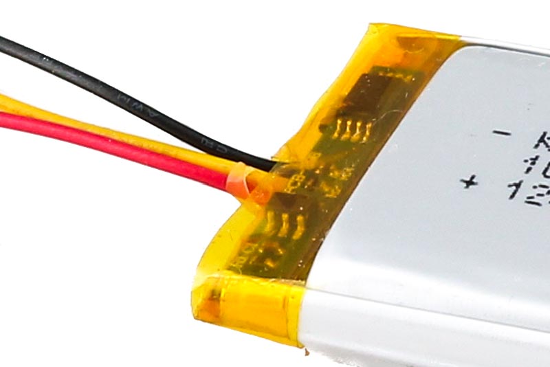
Protection circuit modules are designed to protect lithium-based chemistries from these two hazards. These modules also may be designed with additional features, such as with short circuit protection, temperature protection, electrostatic discharge protection, and power management.
Protection Circuit Module Components
The components of a basic protection circuit module will feature a MOSFET and the integrated circuit (IC). The MOSFET is the control switch. It will switch off the voltage during the charging process when reaching a specified threshold. It will also turn off the discharge of the battery pack when it is discharging too quickly or if the discharge levels become too low during long-term storage. The overcharge and over-discharge thresholds are measured by the IC that will provide the output instructions to the MOSFET.
The IC in the protection circuit module will be designed to measure the voltage of each cell. It will be programmed to shut off the MOSFET to prevent the over-discharge or overcharge of the cell. The control switch will have the voltage measured at both cell terminal ends. So, there will typically be two MOSFETs placed into the design. One MOSFET will be used for overcharge protection and the other MOSFET will be used as over-discharge protection. (Figure 1)
 Figure 1: Example of protection circuit using MOSFET components.
Both MOSFETS will be turned on during normal operation. If the battery cells experience too high of a voltage during charging, the IC will switch the MOSFET used for charge protection to the "off" position to shut off the voltage at the terminals. However, the cell will still be able to discharge through both MOSFETs so long as the MOSFET used for over-discharge protection is still in its "on" state.
The same method holds true for the over-discharge protection process. If the IC detects the battery cells are discharging too quickly or at too low of a state, it will set the MOSFET used for over-discharge protection to the "off" position to prevent further discharge of the batteries. Yet, the battery pack is still able to charge the cells through both MOSFETs so long as the MOSFET for overcharge protection is still switched on.
Additional components involved in the design of the circuit module include:
- Thermistors (monitor the battery cell's temperature)
- Rigid or flexible printed circuit boards (PCBs)
- Resistors
- Capacitors
Additional functions may be added into the custom battery pack. Components and circuitry may be added for fuel gauge protection, electrostatic discharge protection, and code identification.
Protection Circuit Module Design
Depending on the size and complexity of the battery pack, as well as the product, the protection circuit modules may be located embedded within the charger or it may be permanently attached to the battery pack. There are advantages and disadvantages for both design locations.
Embedded in Charger
A protection circuit embedded into the battery charger will only provide protection to the battery cells when the charger is connected. The reason for this design method is to decrease the overall weight for the battery pack. This design may be necessary if the battery pack must be a lightweight design to be fully functional.
Some advantages with having the protection circuit module in the battery charger is that only one protection circuit module will be required, and it can reduce costs when using multiple batteries, such as a product that can also function using non-lithium battery chemistries that do not require a protection circuit when in use or when discharging.
There are several important disadvantages with placing the protection circuit in the battery charger. When the charger is not connected, the battery cannot be monitored when in use to offer active protection. This problem can increase the risks of the battery temperature going above threshold limits and overheating. Also, without the battery fuel gauge and other functions being monitored without the charger attached, the battery pack could experience lower performance and a shorter life cycle.
Embedded in Battery Pack
Protection circuits embedded into battery packs provide full-time protection that is active throughout the lifecycle of the battery. This design method is generally used for rechargeable lithium batteries and where there will be multiple cells within the battery pack. With the protection circuit in the battery pack, it can monitor the battery cells when using different chargers, or when relying on unspecialized power sources to charge the pack. In addition, it can improve the safety of the overall battery pack system, monitor the fuel gauge, and provide enhanced battery performance to increase the battery's shelf life.
Disadvantages for embedded protection circuit modules are that each battery will require a protection circuit module and the combined modules can significantly increase the weight of the battery pack depending on the number of cells that will be in use. Complex battery pack and product designs can make it difficult to place in the protection circuit module depending on the amount of space that is available. Also, costs will be increased based on the number of batteries used as well as the complexity of the design. However, keep in mind that the initial costs of placing the protection circuit module into the battery pack may be recouped due to the extended battery life and greater performance of the battery back.
Battery Pack Configurations
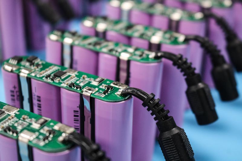
Since protection circuit modules are designed to be placed on each battery pack of the cell, the number of cells placed into the battery is not limited (Figure 2). They can be used for 4-cell, 8-cell, 20-cell, or higher battery packs. To determine the number of protection circuits, as well as battery cells, for the battery pack, the customer will need to figure out the size and rating for the battery system.
 Figure 2: Lithium 4-cell pack with protection circuit.
After examining the product's power needs and the voltage, determine the amp hours of the product.
The formula in determining amp hours is:
Application's required current for operation X the duration of the application's operation = amp hours
Once the customer has determined the required amp hours, next the customer must decide on the battery chemistry that can deliver the suitable amp hours. They may pick between lithium-ion or lithium-polymer cells. Keep in mind that obtaining the exact amp hour rating is not always achievable. In these circumstances, select the battery cells that have a higher amp hour rating than the calculated amp hours for the application. This method will ensure that the battery pack will always meet the application's power needs.
Next, the customer will select the number of battery cells that will go into the pack to provide the appropriate level of voltage. Afterward, the correct protection circuit modules can be chosen and designed for the custom battery pack to use the voltage and is rated for the desired current. Many different companies supply ICs, such as Seiko and Texas Instruments, as well as protection circuit modules.
ICs come in many schematic configurations based on power supply, the number of cells within the battery pack, and the components that will provide additional functions. Considerations to keep in mind when selecting ICs is to determine the thresholds for the overvoltage and undervoltage. The values will be designed into the IC as the customer has a wide variety of choices for threshold mixes.
When selecting MOSFETs, they can come available with low RDS(ON) and low VGS. MOSFETS with low RDS(ON) refers to the amount of power that will be lost when going over the MOSFET as per Ohm's law.
A MOSFET with low RDS (ON) will provide higher efficiency to the battery pack for high-powered operations. When the MOSFET has a low VGS, which refers to low voltage threshold, it means that the IC circuit will only need a lower voltage of 2 volts to 3 volts to drive the gate.
Summary
By having an experienced manufacturer design the battery pack for the application, the customer can obtain assistance with evaluating the types of protections to put into place to prevent the lithium-based battery pack from becoming unstable during charging and discharging cycles to prevent the reactive chemistry from exploding and catching fire within the battery pack.
Placing protection circuit modules within the custom battery pack will ensure that the application will function properly, and that the battery cell's operation will stay within safety measures.
Need Help Designing a Protection Circuit Module for Your Battery Pack?
Our team of experienced engineers is here to help you design a custom battery pack that meets all safety standards and regulations involved with lithium chemistries.
Request a Quote Request Design Support


