When to Use PET and FPC Circuits in a Membrane Switch Design By Steven J. Goodman, User Interface & Cable Assembly Product Manager Epec Engineered Technologies
When a company begins the process of bringing a product to market that contains an HMI (Human Machine Interface), membrane switches are one of the most common technologies selected because of their high reliability, relatively low cost, and level of customization.
Membrane switches are everywhere, just look around, but how many people truly pay attention to the circuit design? Typically, HMI engineers and designers focus on the visible design elements first, such as overlays, pantone colors, and backlighting. Next, the focus is usually on the keypad design, such as the switching mechanism, keypad material, and tactile response. Unfortunately, all too often, designers and engineers fail to provide sufficient attention to one of the most critical design features of a membrane switch, the flexible circuit behind the overlay.
Flexible Circuit Options
Flexible circuit options include polyester (PET) that uses silver ink as the circuit element, and flexible PCB (FPC) that uses copper as the conductive element. Form, fit, and function is very similar for both though their respective costs and reliability can drastically differ.
To understand the impact of using the two circuit designs, it is first necessary to analyze the construction of a typical membrane switch.
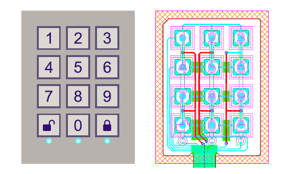 Figure 1: Membrane switch with overlay shown (left) with the circuit layer shown (right)
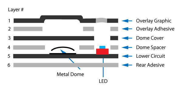 Figure 2: Membrane switch layer cross section
Layer 1
Starting from the outer most layer, the “graphic overlay” is formed with specialized PET or polycarbonate films with printed artwork. This layer serves as the barrier to the environment while containing graphical text, images, and the colors scheme of the membrane switch.
The overlay layer will not be impacted whether a PET or FPC circuit is used.
Layer 2
The overlay adhesive is a pressure sensitive adhesive layer that bonds the overlay to the spacer layers. The overlay adhesive layer will not be impacted whether a PET or FPC circuit is used.
Layer 3 and 4
The next two layers moving inward are the spacer layers. These are also made from PET films. The spacer layers typically serve as electrically insulating layers within the stack-up and help build the overall thickness.
These layers can also help contain dome switches, sandwiching them to the circuit layer. There is no impact to the spacer layers whether a PET or FPC circuit is used.
Layer 5
The circuit layer is the next layer moving inward and resides between the spacer layers and the membrane switch rear adhesive. The circuit layers primary responsibility is to carry the switches electrical signals and provides the most critical functionality of the membrane switch.
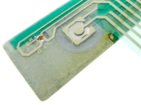
Discrete components such as LEDs, resistors, capacitators and some ICs can be affixed directly to the circuit layer, depending on the circuit design.
Layer 5 (circuit layer) is one of the most critical layers within the stack-up in terms of cost, reliability, and manufacturability. Changing the type of circuit within the membrane switch should not impact any other layers.
Layer 6
The rear adhesive is a pressure sensitive adhesive layer that bonds the membrane switch to the installation mounting surface. This adhesive layer design is critical since it typically serves as the ingress protection barrier and helps ensure no moisture, dust, or other contaminants can enter the mounting surface or housing. The rear adhesive layer will not be impacted whether a PET or FPC circuit is used.
PET vs FPC Comparison
Some customers prefer a “quick n’ dirty”, low-cost product. The PET circuit is an ideal affordable approach. The problem some customers run into is when they experience a change in their requirements. The increased requirements simply are not achievable with a PET design. For instance, surface mount components such as LEDs, capacitors, and even integrated circuits can’t reliably be attached to a PET circuit, especially when dealing with smaller package sizes, footprints, and rugged environment applications.
As you go smaller in package size and add more components, your risk for failure due to an open circuit increases. If you find yourself in a similar situation, look toward the use of a polyimide flex circuit.
The primary reason for the large reliability swing is the difference between the component attachment techniques of PET vs FPC style circuits. PET circuits use a conductive epoxy paste (like glue) to affix components to the circuit pads and traces. This is a proven assembly process and manufacturers have developed methods to surface mount components repeatedly with impeccable precision. However, the bond is only as strong as the mechanical strength of the conductive epoxy, which is why the polyimide FPC circuit is the best solution for high reliability applications.
While the PET circuits use epoxy to attach components, FPC polyimide circuits use a soldered connection that can be up to three times as strong as the conductive glue. If your end application is bound to find itself in environments with excessive vibration, extreme heat or cold temperature swings, or demands high reliability performance, consider a polyimide circuit versus a PET circuit.
PET and FPC Circuit Cost Impact
Polyimide circuits do carry a significant cost commitment in comparison with PET circuits. The reason is simple, polyimide circuits use copper as the conductive element and use lots of it. As copper demand rises and raw material prices climb, this trend is expected to continue.
Customers frequently ask, “What is the cost difference between the two circuit types?”. This question is difficult to answer since there are other design characteristics that can drive cost. A reasonable rule of thumb is that the smaller the membrane switch (in terms of surface area), the lesser the cost impact. Some recent examples to note:
- A 2 in2 membrane switch experienced a ~20-30% cost increase between PET and FPC.
- A 25 in2 membrane switch experienced a ~200-250% cost increase between PET and FPC.
Clearly the larger the membrane switch design, the greater the cost impact between the two circuit designs.
Trace Width Benefits
One of the enormous benefits of using a polyimide circuit would be that you can achieve a much finer trace width. This means you can fit more components in a smaller area and can accommodate unique functionality and characteristics in the membrane switch.
This also means you can reduce the circuit layer count (thus decreasing complexity), and even route traces in and around narrow clearance sections of the layout. Another benefit to employing a finer trace width is the ability to mitigate a unique tail exit location.
Using finer traces can allow for a tail to exit the membrane switch closer to components when compared to a PET circuit. The benefits of polyimide can also be utilized in designs that require fine pitch connectors. If a 0.5mm pitch ZIF tail is a requirement on your membrane switch, PET circuits trace width is too large and can’t support ultra-fine pitch ZIF connections so an FPC circuit must be used.

Electrical Characteristics
Most people are aware of how excellent copper is as a conductor of electricity. That’s why copper is frequently used in wires, circuit boards, etc. The flexible circuit membrane switches make no difference.
If there is a concern with resistance, such as your max circuit resistance needs to be 200Ω or less, you may want to consider a polyimide circuit versus a PET circuit. Just as in a bulk cables’ conductor, the circuit resistance of a membrane switch is a function of the trace cross section, material, and length.
Manufacturing Processes
The PET circuit uses a conductive material that is printed or screened, like what is done with inks on an overlay. Whereas the conductive traces on a polyimide circuit are created through etching processes like circuit boards.
The manufacturing processes of PET and FPC circuits are both carry similar lead times. It should be noted that the membrane switch manufacturing and assembly process is identical whether a PET or FPC circuit is chosen.
PET vs FPC Case Study
To evaluate the performance differences between membrane switches with PET and FPC circuits Epec designed and built two identical membranes to analyze their performance. The goal of this was to assess the reliability, dimensions, and electrical characteristics.
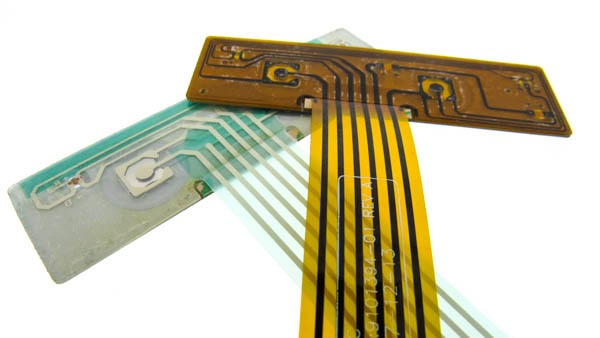 Figure 4: PET Circuit (left) vs FPC Circuit (right)
Listed below is a summary table of key characteristics measured of each design.
| Item | Desc | UOM | Measured Value | % Change | |
|---|---|---|---|---|---|
| PET Circuit | FPC Circuit | ||||
| 1 | Tail Width | mm | 17.54 | 17.56 | 0.1% |
| 2 | Approx Minimum Trace Width | mm | 1.00 | 0.60 | -40.0% |
| 3 | # of Circuit Layers | each | two | one | - |
| 4 | #1 Dome Switch CLOSED | Ω | 30 | 2 | -93.3% |
| 5 | #2 Dome Switch CLOSED | Ω | 31 | 2 | -93.5% |
| 6 | Force to Actuate #1 Dome Switch | grams | 340 | 363 | 6.7% |
| 7 | Force to Actuate #2 Dome Switch | grams | 340 | 363 | 6.7% |
- Tail Width:The ZIF tail width dimensions of both membrane switches were nearly identical. These are cut during the circuit layer manufacturing step and can be customized to any shape or size.
- Min Trace Width:The membrane switch circuit was analyzed, and the smallest trace widths were measured. As expected the FPC polyimide version was able to be constructed with a considerably smaller trace width.
- Circuit Layers:Since the FPC polyimide version can be built with finer circuit trace widths, more traces are able to be fit within the membrane switch footprint. This allows the FPC version to be built with only 1 layer, whereas the PET circuit needed 2 layers to facilitate the same circuit function.
- Circuit Resistance:The pin to pin resistance was measured across the domes of the membrane with the switches both open and closed. The open switch showed an open circuit and no resistance values was measured. For the closed circuit, the resistance of the PET circuit trace was about 15X the resistance of the FPC version. Clearly the screened-on silver ink and conductive epoxy circuit has a far greater resistance when compared to the copper traces of the FPC circuit.
- Tactile Force:The switch actuation force was measured using a calibrated force gauge. Both membrane switches required the same force to close the dome switch. Since the dome switch itself and the overlay/spacer layers drive the keypad’s tactile response, it’s no surprise the two membranes have the exact same tactile response.
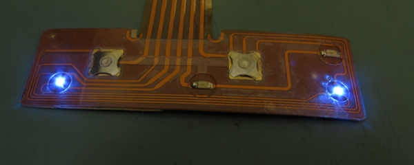
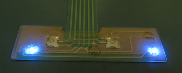
- Reliability:While no firm data was obtained to determine the reliability impact or estimated life between the two designs, feedback was received that showed the FPC design offered a substantial reliability improvement. Specifically, the bond between the circuit pad and the bi-colored LED was improved by switching to the FPC design. Field data showed a significant reduction in open circuit failures of this component.
Summary
At the end of the day, it’s about the impact of failure and what the programs target cost structure is. Every design is different and there is nothing wrong with exploring alternate manufacturing technologies to improve reliability and reduce cost. Epec recommends that a careful assessment be performed on the program objectives, installation environment, and membrane switch design details so that the most appropriate flexible circuit design is chosen.
Looking For a Membrane Switch Solution?
Our team of experienced engineers is here to help you design a membrane switch with the most cost-effective approach for high reliability applications.
Request a Quote Request Design Support


