What Causes Cable Assemblies to Fail and How to Avoid Them By Steven J. Goodman, User Interface & Cable Assembly Product Manager Epec Engineered Technologies
In the industry of electronics manufacturing, cable assemblies, and wire harnesses are indispensable components. They function as vascular systems within a myriad of devices and complex systems, facilitating not just electrical power but also data and signal communications. Yet, for all their critical importance, these assemblies are often the weak link in the chain, susceptible to a plethora of failure modes that can have ramifications on the overall system, causing not just functional disruptions but also safety hazards. These cable failures can impact end-products like medical devices, industrial equipment, and even household appliances.
Failures In Cable Assemblies
Failure in cable assemblies can arise from a multitude of factors. These failure modes can range from breakage caused by a single event- like a forceful tug on a connector, to fatigue damage, which is caused by bending a cable over and over again until the wire or jacket fails. (Figure 1) is an example of a damaged overmold. Or worse yet, prolonged exposure to chemicals and extreme environments can break down the wire insulation making it susceptible to cracking and other types of degradation. These cable assemblies and wire harnesses, often overshadowed by the devices they power, are sometimes overlooked in system design for manufacturability, leading to premature failure and unscheduled system downtimes.
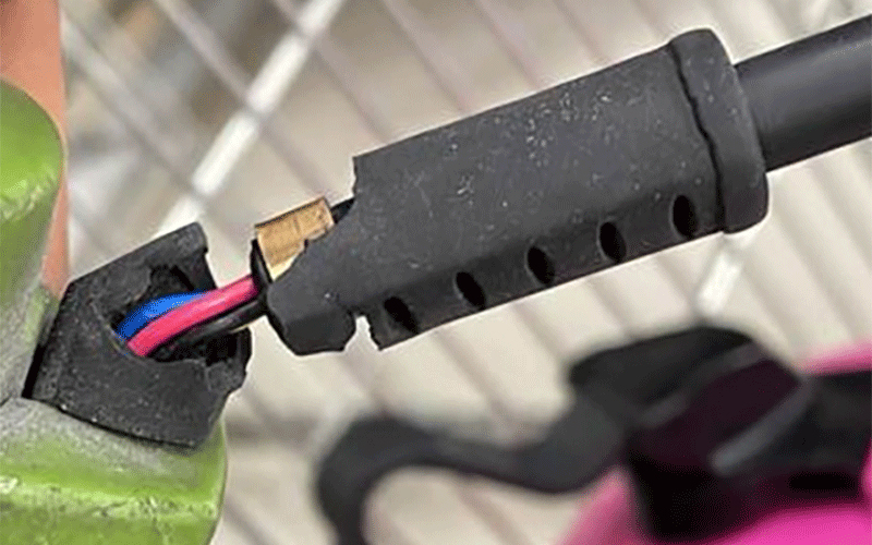 Figure 1: Overmold damaged by bending event with exposed inner wire jackets.
By understanding the unique assembly process of custom cable assemblies and reviewing how each item on the bill of materials goes together, one can better understand the common and not-so-common failure modes of cable. Then, better cables can be designed and built that are able to offer the highest value possible.
What Constitutes Failure in Cable Assemblies?
It's crucial to define what "failure" means in the context of cable assemblies and wire harnesses because there are countless ways these items can break. Simply put, a failure in this context means the cable or wire harness does not perform as intended.
This non-performance can manifest in several ways, including electrical issues like poor signal transmission, complete signal loss, mechanical problems like breaks or damage, or manufacturing defects such as frayed crimp terminations and poor solder joints.
The Complex Anatomy of a Cable Assembly
Cable assemblies are far from simple; they are composed of various types of components and materials, each serving specific functional requirements. When discussing the building blocks of a cable assembly, the primary items are the center conductor, wire jacket, connectors, terminals, and shielding.
The Center Conductor
The center conductor is the most critical part of a cable or wire, facilitating the flow of electrical power or signals. Made primarily of highly conductive materials like copper (Figure 2), center conductors can come in solid or stranded forms. Each stranding option has its own set of advantages and disadvantages, which engineers must consider during the design phase.
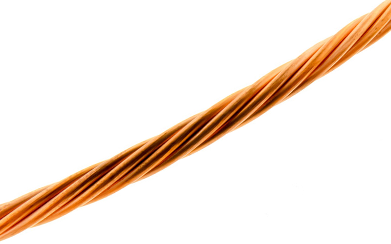 Figure 2: Stranded center conductors help increase overall flexibility of the wire.
Failure of the center conductor is typically the result of an open or short circuit. An open circuit occurs when there is a break in the circuit that prevents the flow of electricity, while a short circuit involves unintended contact between wires or ground, leading to a direct short circuit. The center conductor is highly susceptible to mechanical damage. For example, bending the cable too tightly can violate the wire’s minimum bend radius, resulting in a break and an open circuit. This concern is particularly relevant in applications that involve frequent movement or routing in tight spots, such as in robotics, automated equipment, and CNC machinery.
Wire Jacket
The wire jacket serves as the protective barrier for the center conductors. Generally made from thermoplastics like PVC, XLPE, or PTFE, the jacket shields the cable from environmental factors while providing electrical insulation (Figure 3). Wire jackets are inherently robust but also flexible. However, this flexibility can be a weakness. Flexing beyond a certain limit can lead to the jacket developing cracks or splits, causing a failure.
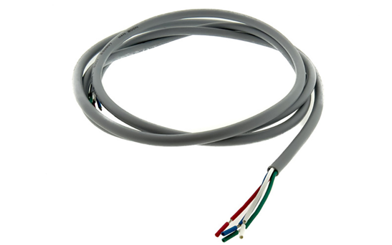 Figure 3: Wire jacketing and insulation separates and electrically insulates the individual conductors.
Environmental factors also contribute to wire jacket degradation. Exposure to sun, UV radiation, or chemicals can cause deterioration over time. Additionally, heat is a major factor to consider when selecting wire jacket options. Each jacket material has its own temperature rating that ranges from 105°C for PVC options to 200°C for PTFE and FEP jacketing options.
Connectors and Terminals
These critical parts are where the wire attaches to other connectors, components, or systems. These types of interconnects are highly vulnerable to mechanical stress, often exacerbated by poor strain relief design measures (Figure 4). According to IPC-620 guidelines, which are the accepted industry standards for cable and wire harness assemblies, proper crimping and soldering techniques must be followed to ensure a secure connection and help maximize reliability.
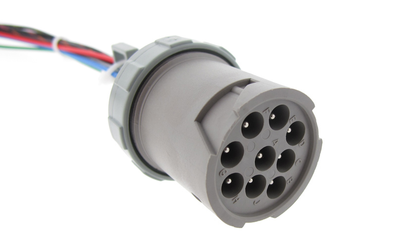 Figure 4: Circular connector with crimped terminals with no strain relief.
Most connectors are rated to survive a range of forces, applied in various directions. This could be caused by someone tripping on a loose power cord, or rough handling during transit. Connector failure can also occur when the maximum allowable pull force (as specified by the original manufacturer) is exceeded. In such cases, the wire or connector would detach, leading to an open circuit.
Shielding and Overbraid
Shielding serves to protect the cable from electromagnetic interference, which is crucial for maintaining signal integrity. This means the shield can protect against harmful electrical interference from entering and impacting the cable.
This also means the shielding layers can keep the signals within the cable and prevent EMI emissions from escaping, minimizing cross-talk with adjacent systems and wire harnesses. The shield layers are made from a variety of materials including a metalized wrapped foil or a tinned and braided copper sleeve (Figure 5). Some wire harness manufacturers invest in specialty equipment which can overbraid directly onto a completed wire harness, helping improve the overall shielding coverage and strength.
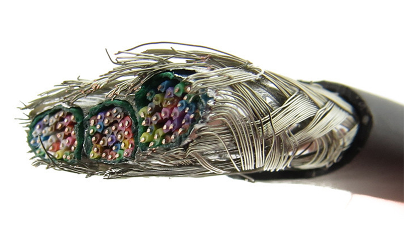 Figure 5: Tinned copper braid wrapped around multiconductor cable.
Shield failures often arise from an inadequate shielding design, or selecting the wrong basic shielding scheme when high levels of EMI shielding are necessary. Also, bending and abrasion can wear away the wire jacket and damage the shielding layer. If a drain wire is used to terminate a foil shield to ground, the drain wire itself can become damaged or break creating an open circuit with no shielding reference to ground. Any gaps or breakdown in the shield along the wire jacket can cause EMI energy to leak and negatively impact other systems and equipment, potentially causing a failure.
Industry Best Practices for Avoiding Failures
To minimize the likelihood of failures, open circuits, and short circuits in custom cable assemblies, several industry best practices have been adopted:
- Prototyping and Testing: One of the most effective ways to anticipate potential issues is to build samples for rigorous testing and focusing on this early in the project. This helps in identifying weak points in the assembly and helps affirm that the cable will meet all required performance requirements.
- IPC-620 Compliance: This industry standard provides guidelines on assembly methods, workmanship criteria, and testing requirements for wire harnesses. Specifically, this specification helps define good vs. bad assembly and workmanship techniques that would otherwise impact the reliability of the harness.
- Material Selection: Always ensure that the materials used are appropriate for the application. Some applications require high voltage, extreme temperatures, ruggedized construction. Engineers must do their due diligence and research materials options before launching any new build. For example, if a cable is going to be exposed to high temperatures above 150°C, materials like PTFE or silicone would be more suitable than PVC.
- Mechanical Safeguards: Proper strain relief is among the most effective ways to prevent cable damage. Everyone has been guilty of yanking on a cable too hard and watching the prongs bend, backshell loosen, or just fail completely. Various types of wraps and sleeving can be employed to protect the wire bundle from rough handling and wear, further improving reliability. While there are several industry standards for options to strain relief and protect a cable, design engineers have the ultimate responsibility for choosing the most appropriate option in terms of cost and protection.
Summary
There are literally countless ways that a wire harness can fail, and over time as the harness sees more and more real-world abuse, the likelihood of an open or short circuit will increase. Failures can arise due to a variety of reasons including material degradation, mechanical stress, and improper assembly methods.
Ensuring the reliability of the wire, connectors, and jacket thus requires a multidimensional approach, encompassing robust design, stringent quality control, and an in-depth understanding of the application environment. However, with thorough engineering analysis, guided by industry standards like IPC-620, and complemented by experienced cable manufacturing, these failures are not just explainable but also largely preventable.
Need Help Avoiding Cable Assembly Failures?
Regardless of the applications, our team of engineers can help guide you through the development process all the way through to production, ensuring a high-quality product.
Request a Quote Request Design Support


