
Microcontroller-Based Hot Swapping of Batteries By Anton Beck, Battery Product Manager Epec Engineered Technologies
There are several reasons why batteries need to be hot swapped in the field, during operation, and each of these reasons may require different hot swap techniques. Some battery applications require continuous uptime or have no time for a recharge cycle during operation. These are normally portable life support-type products or critical robotic systems in constant motion.
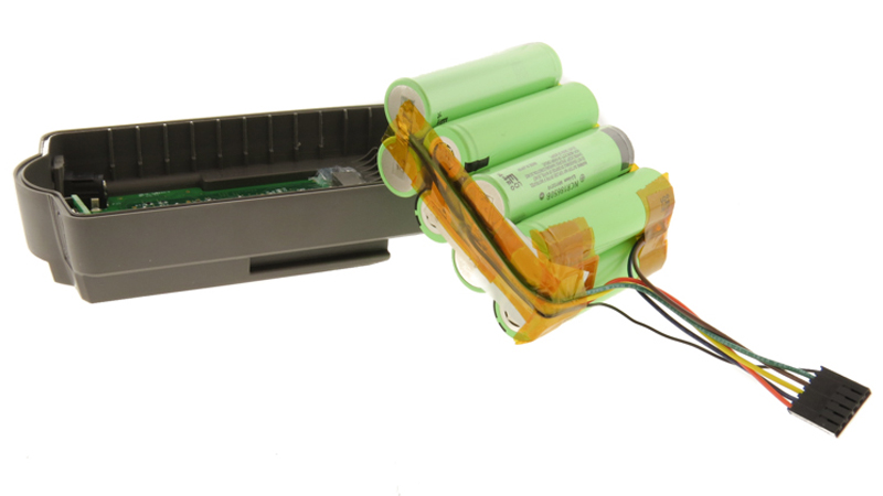 Custom battery pack for portable device tool using a slide-on mechanism.
Other battery applications require continuous uptime but have time to recharge and can detect when a battery is at the end of life and a new battery needs to be installed without downtime. These types of systems require multiple batteries, so when one battery is being replaced the other battery/batteries in the system can keep the system powered. These two types of applications usually fall into two different methods of hot swapping: simple “high battery” hot swapping and “voltage matching” hot swapping.
Simple “High-Battery” Hot Swapping
Simple high-battery hot swapping is normally simple. The concept is that as the batteries in the system drain, there will be a fuel gauge that provides a state of charge for each battery. Portable systems may not be near a power source to provide power during a battery swap. Under these situations, two parallel batteries are required to be installed in the system, so when one is removed, the other is sized large enough to handle the load on its own. When the battery is removed, a fully charged battery can be installed … or can it?
Keep in mind that a fully charged battery regardless of chemistry has a higher voltage when fully charged. If the fully charged battery were to be installed, it would try to discharge a lot of its energy into the discharged battery which is still in the system.
Unlike jumping a dead car battery, which has the advantage of fairly high-impedance jumper cables and high-impedance dead cells, industrial and medical li-Ion batteries are generally low-impedance devices that can deliver a lot of power.
Depending on the size of the battery, simply installing a fully charged battery in parallel with a discharged battery can create a lot of excitement. A large amount of current will flow from the fully charged battery into the discharged battery causing large sparks welded connectors, blown fuses, and damaged cells. Discharge specifications for the fully charged battery will be violated and the charging specifications for the fully depleted battery will be exceeded. Resulting in the likelihood of damage to both batteries. This problem is only compounded if there are many batteries in the system.
To prevent this from happening, the batteries need to be isolated from each other. This can be easily done by using two inexpensive diodes (Figure 1).
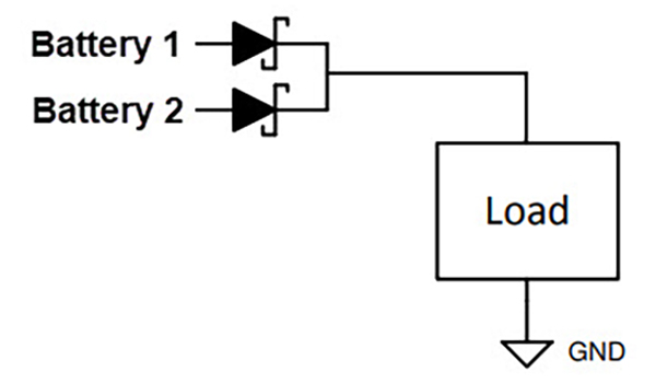 Figure 1: Diode ORing Power select
This method works well when using higher voltage batteries when the diode drop of 0.35-0.7V is less noticeable. Schottky diodes provide less drop, but unfortunately, this lower voltage drop still wastes and can be a heat source in high-current applications. The diodes will also reduce run-time.
Another more expensive solution is to use a FET-controlled circuit (Figure 2).
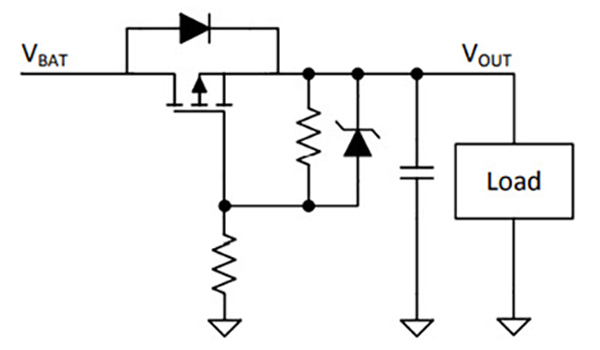 Figure 2: Reverse battery protection using P-Channel MOSFET
Or an ideal diode IC. Both of these circuits reduce the “diode” voltage drop to near zero; hence reducing heat, and more run-time (Figure 3).
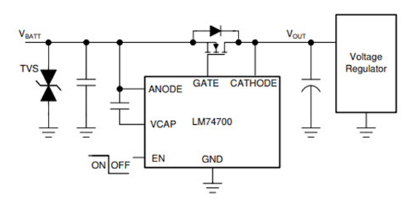 Figure 3: Ideal diode controller.
All these methods allow the highest voltage battery to supply power to the system while the discharged battery can be safely removed for charging or replacement with a charged battery, so there are two fully charged batteries.
“Voltage Matching” Hot Swapping
The above hardware solutions are great when the application only requires swapping out a low battery and replacing it with a fully charged battery. The above methods don’t work if a system can charge and discharge batteries and the system flags as a bad battery that needs to be replaced. In this case, the batteries can be in any state from fully charged to discharged.
Without having a skilled technician on staff to know exactly when to remove and insert a new battery, fireworks can happen.
New Battery In an Unknown Charge State System
Epec has developed methods using firmware and microcontrollers to allow battery insertion into an active system without harming the batteries in the system or the new battery. Best of all the new battery can be in any charge state. Normally it is charged to 30% right out of the box.
Multiple batteries can operate in one system and can be at any charge state. When it becomes time to swap out an old battery, the old battery can be removed, and the new battery be simply inserted at any time and at any charge state.
How is this possible? We use a microcontroller in each battery to look at the rail voltage before allowing the battery to connect to it through its safety FETs. If there is no voltage meaning that it is the only battery in the system, it will turn on its output to power the rail. If subsequent batteries are installed, they will also look at the rail voltage. If the voltage is a close match, they will connect to the rail when appropriate. If the voltage is out of sync, which occurs if some batteries are fully charged and the other batteries are fully discharged, the batteries will wait to connect until the voltages either come up or down to their respective voltages.
As the system is either charged or discharged, the new battery will see when it is an ideal time to attach itself to the rail. In the event the system is not being used, we help the process along by allowing batteries higher than rail voltage to discharge some of their energy through a power resistor onto the rail and batteries lower than rail to charge their batteries through their power resistors. Once the battery is close to the rail voltage the power FETs activate, and the power resistors are turned off.
Below is a simplified schematic showing the FETs, power resistors, and hot swap microcontroller (Figure 4).
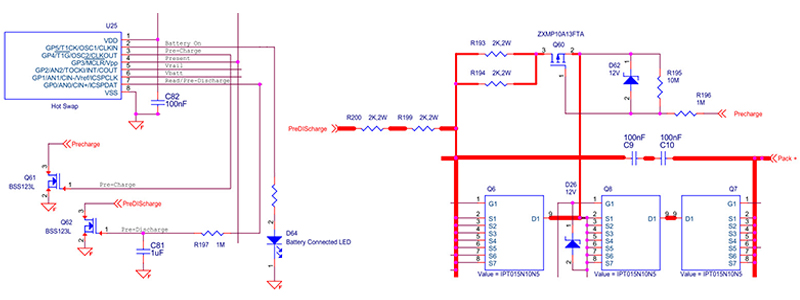 Figure 4: Microcontroller hot swap method.
Summary
Batteries used in portable power products that require continuous power must have multiple power sources, which can be two or more batteries in parallel capable of supplying supply power to the system when the batteries need to be serviced. Depending on the application different approaches are used for either technical or cost reasons.
It is rarely a simple task with today’s batteries to achieve hot swapping without adding circuits that prevent unleashing large amounts of destructive currents or tripping sensitive safety circuits. These unexpected events can bring down an entire system. Here at Epec, we have a lot of experience with large and small-format multi-battery systems and have developed many solutions that perfectly fit every application.
Looking For A Custom Battery Pack?
From design to production, our team of experienced engineers at Epec are here to help you design a custom battery pack for a variety of applications.
Request a Quote Request Design Support


