
Acoustic Switch Technology Offers Rugged Capabilities for HMI's By Paul Knupke Epec Engineered Technologies
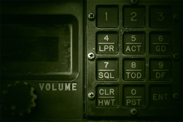
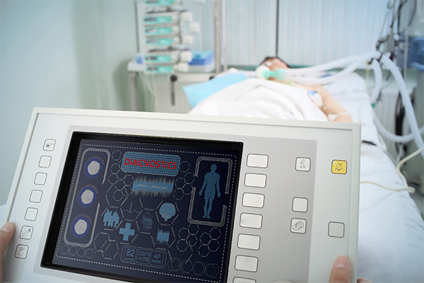
As devices in all industries become more portable and require functionality in different harsh environments, integrating acoustic switch technology into any Human Machine Interface (HMI) design adds to the user experience and the durability of a product.
Acoustic switches overcome traditional switch technology limitations as it based on a human operator's finger absorbing acoustic ultrasonic energy as the means to sense the intent to operate a switch. One important feature is the finger does not move any part of the switch to cause the switch to work. Therefore, there are no moving parts to the switch, meaning the switch is a finger-operated solid-state switch.
The technology is very similar to current touch screen technology in how it functions however, when integrated with LCD's, graphics or even traditional touch screens, it makes the entire HMI much more rugged.
Specific Benefits of Acoustic Switch Technology
- Extremely Rugged Construction:Acoustic switches are fabricated with a solid metal plate 1/8" or thicker.
- Vandal Resistant: No vulnerable parts are exposed to the user. The solid metal plate cannot be pierced with a screwdriver or dented with a hammer.
- Impervious to Exposed Outdoor Environments:Switch operates reliably in freezing rain, tropical heat, dust storms, and within temperature ranges of -40°C to +80°C.
- Underwater Operation:Operated by energy absorption from a finger. Not operated by pressure and is insensitive to water i.e. water pressure and will not activate acoustic switches.
- Waterproof:Naturally waterproof to the edge of the solid metal plate where normal seals can be used to seal against the enclosure. This is perfectly suited for National Electrical Manufacturers Association (NEMA) and IP65 enclosures.
- Explosion Proof:No closing or opening electrical contact surfaces that can cause an arc.
- Self-Diagnostics and Failure Detection:Constantly sensing untouched ring-down oscillations provides failure detection and notification before the acoustic switch is pressed.
- Resistant to Aggressive Cleaners and Solvents:Solid metal operator surface is safe for pressure cleaning and solvents that normally attack plastic switch surfaces.
- Self-shielding:Solid metal plate construction functions as a natural Electromagnetic Interference (EMI), Radio-Frequency Interference (RFI), and Electrostatic Discharge (ESD) shield.
Integrated Technologies
Acoustic switches can be integrated with other technologies to create cost effective and visibly efficient user experiences. Below are some typical examples of the different technologies that can be combined with acoustic switched to create effective HMI's.
- Rubber Keypads/Membrane Switches:Many applications require the durability of the acoustic switch but the user still needs a tactile feel to operate the device. By integrating a rubber keypad of membrane switch the user feels the switch being actuated even though it is not necessary to trigger the switch. Aerospace applications are where this method is frequently used.
- LCD's:By using displays in the HMI we can create a user experience with exceptional functionality as the outer rim of the display is surrounded by a rugged acoustic switch matrix. We can then program the software and firmware to create the user experience as the buttons are actuated until the display prompts for a user input.
- Backlighting:By using LED's or incandescent back lighting, the buttons on the switch can be illuminated in different fashions. The entire unit can be backlit or we can program the software to guide the user through the experience by selective lighting using light guide panels.
- Touch Screens:While this technology is very similar to touch screens, it has significant advantages including being water resistant.
How Much Does This Effect Cost?
The biggest question we receive on this technology is about the cost because of all of the benefits that it provides. With experience in developing this technology we're capable of keeping the overall cost difference to traditional switch technology to only 10-15% in most cases. There is however significant cost differential in the life of the product and customers often experience a 100% increase in the life of the HMI even in high use applications.
Technical Overview of Acoustic Switches
It is always helpful to try to understand a little about how this technology works. The acoustic switch has a resonate element also called a resonate cavity. This resonates at a specific frequency when energy is applied for a brief moment. Physics has shown that the applied energy can be directed and isolated to a defined area even if the resonate cavity is part of a larger piece of material. This allows for multiple resonate elements to be contained in a larger, single piece of material to form a physical switch array. Practical acoustic switches are made from solid aluminum or stainless steel sheets. A resonate cavity is created between the outer surface (operator touch point) and the rear surface. Energy is transferred to the resonate cavity by means of an ultrasonic transducer that is mounted to the rear surface of the metal sheet. The ultrasonic transducer has two purposes. It first must generate an acoustic energy burst that is transferred to the resonate cavity. It then must sense the magnitude of the oscillations during the energy decay over time.
One of the key elements of the acoustic switch is directing and isolating the energy to a defined area. Figure 1 shows the rear surface of a section of metal sheet with an ultrasonic transducer attached. Surrounding the transducer is a shallow circular depression. The inside diameter of this depression is the feature that redirects the energy from the surface of the metal plate to the opposite face of the metal plate. Acoustic switches can be mounted very close to each other on the same metal plate with a high level of signal isolation so that switches do not interfere with each other.
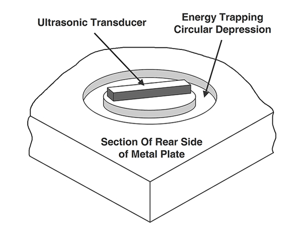 Figure 1: Transducer and Energy Trapping Depression
The transducer has two metalized surfaces. One surface is attached to the metal plate and the other surface is the opposite exposed parallel plane. An electrical connection is made to the exposed plane with a low mass connection such as a spring. Interface electronics are mounted immediately behind the ultrasonic transducers to maintain transducer signal integrity. This connection should absorb little of the acoustic energy for best acoustic switch operation.
The ultrasonic transducer provides a burst of energy to start the ultrasonic oscillations in the resonate cavity. It then operates as a listening device for sensing the length of time for ring-down. The acoustic switch does not know when a human operator will touch the switch. The acoustic switch must be energized with the oscillation ring-down sensed on a continuing, frequent, basis (as little as 200 microseconds. Figure 2 shows one of these energizing and ring-down cycles. The ultrasonic transducer is energized with a burst of ultrasonic energy in the vicinity of 1.5 MHz to start the oscillation. There is a short delay shown in the graph as a gap in signal where the transducer is electronically switched between a driving device and a sensing device. After the transition, the transducer senses the peak amplitude of the ring-down oscillations as a decaying logarithmic curve. An arbitrary threshold level is established as noted by the red line. The electronic circuitry counts the number of times that the amplitude of the oscillations crosses the threshold level until the oscillations decay and no longer cross the threshold level. The count of the times the oscillations crosses the threshold level is an indication of the "normal" untouched switch decay time.
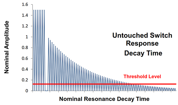 Figure 2: Untouched Acoustic Switch Transducer Signals
Figure 3 shows the same acoustic switch while being touched with a human finger on the opposite face of the metal plate. The finger absorbs some of the acoustic energy so that the number of ring-down oscillations crossing the threshold level is fewer than the untouched acoustic switch. As soon as a finger is removed, the ring-down curve reverts back to Figure 2. A comparison of oscillation count above the threshold level provides the indication of touching the acoustic switch's front surface.
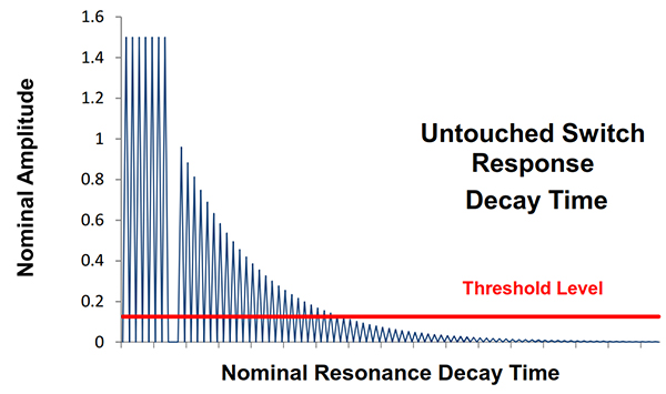 Figure 3: Touched Acoustic Switch Transducer Signals
Acoustic switch electronics can mimic any standard interface protocol. The electronics can sense any performance degradation from normal that may indicate a future potential failure before the failure is detected by the operator as a non-functioning switch. This diagnostic feature is distinctly unique to acoustic switches and is being used in critical applications.
The front surface solid metal plate (user's side) can be marked using engraving outside of the footprint of the circular depression around the ultrasonic transducer on the rear side. Laser marking will be over or around the footprint of the circular depression around the transducer or a plastic or metal overlay next to or around the circular depression. Energy absorption by the users' finger can be hindered with other materials over a resonate-cavity area, such as typical plastic or metal graphic overlays. The tradeoffs for some decorative limitations are vastly improved environmental specifications, ruggedness, and reliability. This also includes self-diagnosis and failure reporting capability not found in other switch technologies.
Summary
If you need acoustic switch technology we will work with you regardless of industry to create custom single switches, keypads, and/or integrated HMI assemblies. Each design is engineered specific to the application where other available switch technology does not perform well or for applications in harsh or hazardous environments.
Looking For a Rugged Reliable HMI?
Working on countless military, aerospace, and medical applications, our team of engineers can help you design and manufacture various types of human-machine interfaces for both new and existing programs.
Request a Quote Request Design Support


