
Developing Custom Test Fixtures for MIL-DTL-38999 Cable Assemblies By Steven J. Goodman, User Interface & Cable Assembly Product Manager Epec Engineered Technologies
Mil-spec cable assemblies conforming to Mil-DTL-38999 are known for their ability to survive the toughest of conditions, their high reliability, and their capacity to function in mission-critical settings. This also means that these mil-spec cable assemblies are among the most complex cable types that exist where costs can exceed several thousand dollars per cable. These high costs come from the expensive wire and connectors used and from the fact that certain custom cable assemblies can take dozens of hours to assemble.
Considering the cost and overall impact of an anomaly where the cable doesn’t work properly, what is the point of spending all this time and money to assemble a cable only for it to break or fail prematurely? Testing of mil-spec cables is absolutely necessary at the development stage and again during full rate production.
What is Mil-DTL-38999?
Mil-DTL-38999 is a widely known military standard that covers circular connectors terminated to cables with either crimp connectors or solder cups. This specification states that connectors shall be environmentally sealed and rated for temperatures of -65°C to +200°C. Within the family of Mil-DTL-38999 connectors and terminated assemblies, there are options for high-density, bayonet, jam nut, and panel mounting interconnects to name a few.
Since Mil-DTL-38999 connectors are known for their extensive lead times and costs, design engineers must carefully select the precise combination of features before deciding on a connector scheme and the exact part numbers for the plugs and receptacles.
Mil-DTL-38999 Cable Assembly Test Options
When most think of testing options for Mil-DTL-38999 cable assemblies, continuity is among the most common tests performed. Continuity checks are inherent in the electronics industry and can be automated allowing for rapid and efficient measurements (Figure 1). Other common electrical tests include hi-pot, insulation resistance, and electrical bonding. While these tests are necessary to verify the cable workmanship, these tests do nothing to actually stress the cable for how it will be used. Additional tests and fixtures are likely needed to fully evaluate the cable and confirm it meets all design requirements.
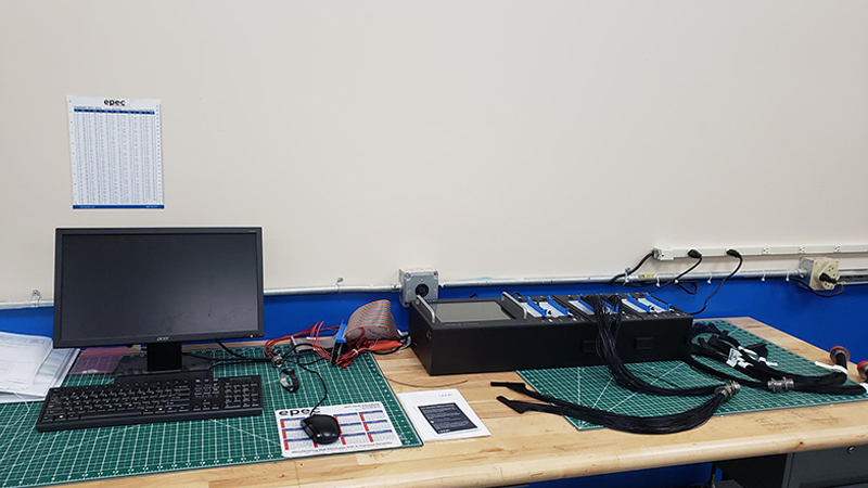 Figure 1: Automated electrical test stations can perform hundreds of measurements in a single test.
Functional Test Considerations
Functional testing is difficult due to its broad scope, especially as it relates to custom cable assemblies. Designers must develop a comprehensive test plan that fully evaluates the cable, and in doing so may need several custom test fixtures designed. Because of this, each individual test must be studied to define the necessary test parameters and build the supporting equipment.
Also known as an acceptance test procedure, these types of tests are developed to verify that the cable does the job it’s intended to do. Functional tests may involve plugging the cable into a mating assembly and applying power, it may involve movement or flexure of the cable or even driving high-resolution video or high-speed data across the cable. What good is a custom cable if it does not perform the job it was designed to do?
Ultimately, it’s the responsibility of the design engineer and the end customer to agree upon the necessary functional tests that are required, and when they are performed. It’s then the job of the cable assembly manufacturer to help develop a plan to meet these requirements, and to design and create the necessary custom test fixtures.
In-Process Test Considerations
Industry best practices recommend that in-process inspection is performed at critical points in the assembly operation. For example, there are process points of no return where an operation cannot be easily reversed or reworked, and accordingly, it’s recommended to structure these in-process inspection points strategically before these events.
The famous carpenter’s proverb measure twice and cut once holds true for manufacturing since it’s necessary to properly plan before taking action. Common in-process tests that may require specialty fixtures include electrical measurements, length checks, flexibility tests, etc.
Other in-process checks that are specific to Mil-DTL-38999 style connectors can involve making sure that any polarization features or mating keyways are properly configured. Many high-density circular connectors feature keyed slots to make sure there is proper alignment during the mating of assemblies. These features help ensure that correct pins match up to the corresponding sockets, with an example being that PIN 1 on the plug lines up with PIN 1 on the receptacle.
Additionally, since many of these finished cables can be bulky and cannot freely rotate, the connector orientations relative to one another (and relative to their mating connector) are equally important. Also called clocking orientation, design engineers will specify the degrees relative to a known datum to define all keyways and their clocking orientation (Figure 2). Typical clocking orientation tolerances are +/- 15 degrees. Building test fixtures to check in-process cables clocking orientation may be necessary to prove that the cable will properly fit within the next higher assembly.
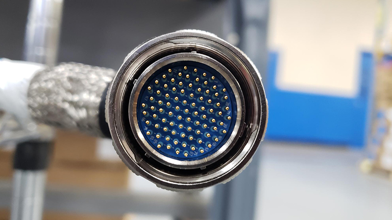 Figure 2: Keyways in circular connectors are critical to ensure a proper alignment.
Other in-process tests and fixtures may be necessary to measure the overall length of the harness, and check that any breakouts or splits in the cable are located properly.
Concerns for Developing Custom Test Fixtures
Since custom test fixtures are expensive and considering the fact that they will take time and resources to build, it’s important to properly plan out each individual fixture (Figure 3) that is necessary well before it’s actually going to be needed. Engineers will gather all project requirements and brainstorm the types of tests that are required. Reviewing the considerations below can help reduce time, cost, and risk from the looming testing needs for your new Mil-DTL-38999 cable harness.
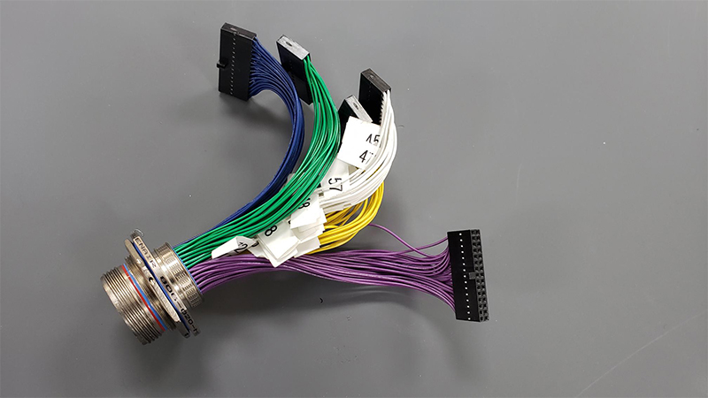 Figure 3: Custom interface cable for electrical test.
Test Parameters
One of the most critical steps in the entire project is to clearly define the test parameters, and the appropriate pass/fail criteria. Without this information, a good product can fail, or a failing product can make it out to the field. Clearly define the test parameters, specify the appropriate measurement units, and clearly document the test conditions and units.
For example, and because of the effects of alternating current, performing an AC hipot test at the same DC hipot voltage can actually over-test a cable and render a failure. This is because DC hipot tests are usually performed at the equivalent AC peak voltage.
Long Lead Times
It’s likely that many of the items necessary to assemble your new test fixture will need to be purchased. These items include components such as wire and connectors, and also hand tools such as crimpers, and insertion/extraction tooling. It’s also likely that there is expensive test instrumentation or a data acquisition system that needs to be purchased.
All these items should be assumed to be a long lead time until proven otherwise! Waiting too long to purchase the materials and test systems necessary for your custom test fixture can put undue strain on your program plan. Check lead times frequently and issue purchase requisitions as soon as possible.
Documentation
All test equipment and fixtures need the proper documentation. This includes assigning a part number, managing revision control, and all the other necessary documentation. For higher complexity tests that may involve an electrical schematic, including the proper information to troubleshoot an electrical circuit is necessary.
One of the worst potential issues for your project is for your manufacturing engineer to spend six months building an automated test station, only for them to leave the company before completing the documentation for the next engineer taking over the project.
Assembly
Underestimating the complexity and total labor hours needed to assemble custom test fixtures can significantly impact a development schedule (Figure 4). Don’t lose sight of who will have to build it and make certain that they are properly trained and qualified. Assembling 180 crimps and wires in a high-density connector can be extremely challenging and should not be a task that is tabled for the end of the schedule.
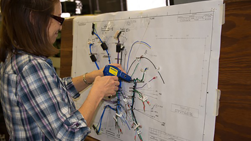 Figure 4: Cable assembly layout boards are used to verify high complex builds.
Summary
Since the ultimate goal of building custom test fixtures is to make sure that the associated Mil-DTL-38999 cable harness functions as intended, the subject of test fixture design needs to be a priority.
Careful planning is needed early in the project to gather information on the types of tests that are required and the supporting equipment that will be needed to perform the job. Scheduling these tasks and material buys early is important because of the lengthy lead times that many of these components will have.
See our blog post on substituting cable assembly connectors for more information.
Looking for a Mil-Spec Cable Assembly Conforming to Mil-DTL-38999?
Our team of experienced engineers is here to help you design a custom cable assembly solution using the highest quality cable and components to meet the exact form, fit, and function of your requirements.
Request a Quote Request Design Support


