Best Practices for Custom Cable Assembly Drawings By Steven J. Goodman, User Interface & Cable Assembly Product Manager Epec Engineered Technologies
One of the first steps for any new design project is to create an engineering drawing. Sometimes called a print, blueprint, or specification, the goal of this document is to create the proper documentation to define and manufacture a widget. For some projects, the level of documentation required is significant, such as in a printed circuit board assembly or a full box build. For other projects that require lower complexity products, such as stamped sheet metal or a single grounding wire, the overall documentation necessary to manufacture the part is greatly reduced.
The amount of documentation required depends on the number of components within the assembly, their respective level of complexity, and if any of the required subcomponents are considered off-the-shelf hardware. A drawing can be simplified if the majority of the bill of materials (BOM) is readily available through standard distribution channels such as McMaster, Mouser, or Digikey. A drawing consisting of a standard wire type, ring terminals, and a few labels can be simple while being sufficiently defined.
A drawing's complexity is also driven by the application. The amount of documentation necessary for a medical device cable assembly drawing is significant and typically includes information such as the material type, temperature and flammability ratings, REACH/RoHS compliance, or more. These details are not only considered best practices for medical industry drawings, but they may also be a firm requirement.
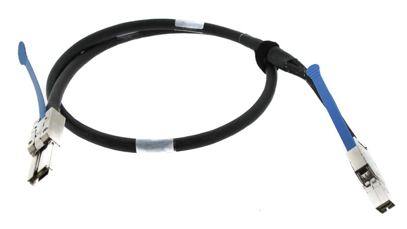
Military and aerospace applications are also known for their complex specifications and drawing requirements (Figure 1). Many military and aerospace cable assemblies reference industry specific standards known as MIL-specs, process related specifications, and even federal standards such as DFARS.
 Figure 1: Custom cable assembly with complex specifications and requirements.
Cables assemblies themselves vary greatly in complexity and technology. Accordingly, so do the manufacturing drawings that define them. Most cable assembly drawings contain some sort of length information, a BOM, and an electrical schematic that shows the wiring configuration. As the design complexity increases, so does the amount of information required to define the cable assembly.
For cable assemblies that include overmolds and miscellaneous components like motors, fuses, and PCBAs, additional documentation may be required to thoroughly capture the design and assembly requirements. Before any new custom cable drawing is started, it is important to clearly understand what the drawing will be used for and the level of documentation required to support the project.
When to Consider a Drawing for your Cable Assembly
Some type of drawing is required for all custom cable applications. The earlier a drawing can be started, the better for all parties involved. As engineers, buyers, and managers navigate the demands of any new development project, having a clear cable assembly scope of work allows for the supply chain to be setup and potential make/buy decisions to be evaluated.
Before starting a custom cable drawing, it is important to determine what you trying to accomplish with the drawing.
Goal #1: Preliminary Concept Cable
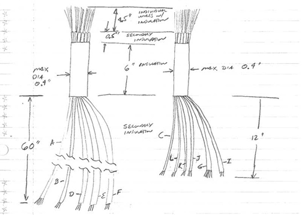
For many projects, the very first cable assembly drawing generated is some type of "napkin sketch" (Figure 2). While this doesn't have to be written on a napkin or jotted down over a beer or coffee, some type of initial sketch is necessary early on to get things started. The primary goal at this point in the project is to create a visual tool to help gain stakeholder input. While many questions remain, some questions that can be answered because of this activity are: "is this cable design even feasible," or, "does this solve our design challenge." These preliminary concept cable drawings are ideal for brainstorming and collaboration sessions.
 Figure 2: Example of a cable assembly napkin sketch.
For this preliminary concept drawing to be effective, it needs to be created fast. Taking one week to create this type of drawing or sketch completely negates the purpose. This drawing should contain a rough sketch of the configuration, the number of circuits, the overall length, and any critical design needs or concerns. The simpler and faster this can be completed, the better. And it is likely that this type of drawing must be supplemented by a verbal or written explanation.
Goal #2: For Quotation Only Cable
As companies look to bid on and capture new manufacturing opportunities, one of the most important deliverables in this process is a proposal or quotation. These documents capture the costs, timelines, and bid assumptions, allowing manufacturers to seek out and win new business opportunities. One of the most critical steps in this process is soliciting supplier quotations that feed into a larger scope of work. Professionals use the terms "bid for bid" or "bid for buy" to characterize the type of manufacturing opportunity and provide context on the project. As the namesake suggests, one quotation is supporting a proposal, and the other type of quotation is stemming from a firm buy requirement. This is important because the level of detail required for each, and the potential cable drawings necessary to support this activity can vary significantly.
At this point, many companies seek out what is referred to as a "budgetary" or "ROM" (rough order magnitude) quotation. To support a budgetary or ROM quote, the information that is required on the drawing includes the BOM, the approximate cable length, the wire type, and if there are any unique or complex design challenges. If a more precise quote is required, the cable assembly documentation must support this.
Generally speaking, if the cable drawings' goal is to only gather cost data, many elements of the "napkin sketch" noted within still apply. It is important to have a drawing completed fast, but the document needs to be clear and concise allowing the supplier to understand the scope of work. It is also important to note any special test requirements above and beyond continuity since additional testing can can impact both the price and lead-time. If there are any raw material lead-times or minimum buys that could impact price, it is important to be able to have this review done during this step.
Goal #3: Prototype Cable Assemblies
Prototype cable assemblies are used for fit checks, testing, and other types of evaluation early in the project. The ultimate goal of a prototype cable is to help reduce risk in the project and determine if the design is satisfactory. While some prototype cables aren't pretty, if the cable works as intended and can be manufactured quickly, it's served its purpose. Cable manufacturers have developed clever ways to help reduce the time to market while offering high-quality prototype cables.
Some manufacturers have segregated manufacturing cells than can focus on quick-turn prototypes without impacting higher-volume manufacturing operations. For example, an overmold tool can be built using 3D-printed plastics allowing for rapid development. While these 3D-printed tools can yield production-worthy cables, these are inappropriate for higher volume manufacturing since they will wear and breakdown over time. Some overmolds themselves can be 3D-printed and bonded to the cable to allow for fit checks when performance is less critical. As long as the cable electrically functions or offers some type of dimensional semblance to the mature product, meaningful data can be obtained.
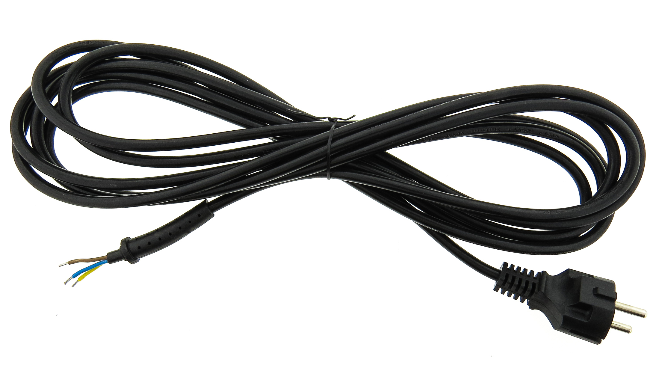
 Figure 3: Example of a prototype cable assembly.
Custom cable manufacturers like Epec employ a sampling process that delivers production-worthy cables in advance of volume production. The cable drawing information that is required at this point can vary significantly with the application and complexity. The connector design and overall length remain the most critical aspect of the prototype cable (Figure 3). Any prototype drawing should at the least contain this information.
Goal #4: Production Cable Assemblies
As manufacturers move into full rate production, the information contained within the cable drawing is especially critical. With production comes some type of volume build, whether it's 100, 10,000, or 100,000 pieces, any drawing issue can manifest itself as an enormous scrap cost or delay.
Ideally, production drawings must go through an extensive review process allowing for all stakeholders to review and approve the design. A design for manufacturing review must be performed to make certain that the cable is manufacturable, and ideally this should have been completed between the prototype and production stages. Whether it's a formal engineering change order (ECO), or manufacturing proof approval, all production cable assembly drawings must be scrutinized before production commences.
In order for a cable drawing to be completely defined, it must contain all relevant specifications and requirements. This includes a complete BOM that lists all components required to build the cable. The BOM must contain specific information relating to the parts lists that includes the wire size and specification, component P/N, the unit of measure, and the quantity used per assembly. Additional information pertaining to the shielding of the cable and wiring pinout must also be clear. If there are critical dimensions on your cable that must be taken into consideration, adding detailed section views and notes are invaluable. The more information, the better.
Additional programmatic requirements must also be included in the production drawing. Any export control or ITAR designations need to be clearly noted on the drawing in the appropriate title block location. If there are specific functional tests or electrical testing that is required, this must be clearly shown such that the process is repeatable.
Pull tests, flex tests, and other mechanical tests that need to be defined and at what interval. Should these cables be 100% tested? Or do the requirements apply to the first-time build? The more information relating to the overall requirements, the better.
Summary
Engineering drawings have been used for centuries to define how to build and assemble items. Many of these drawings transcend languages and borders, allowing teams from across the globe to review and collaborate. If the drawing can be understood by engineers on the other side of the world, it has served its purpose. Cable assembly drawings are no different, especially since many custom cable assemblies are manufactured overseas. While there are best practices pertaining to drawing views, pinout identification, wiring, and schematic notes, what's important is that the information is clear and indisputable.
Since one of the most challenging aspects of creating a custom cable drawing is knowing what information is needed, early engagement with a capable manufacturing partner like Epec is imperative. But just as important is the need to determine what the drawing will be used for. It is clear that the level of information required, and the amount of time invested differs greatly between the types of cable drawings that can be created. At the very least, defining the connectors, wire type, and length can help start the process that will eventually become a complete and effective piece of documentation.
Need a Custom Cable Assembly But Not Sure Where To Start?
Whether it’s military, aerospace, or medical deviceapplications, our team of engineers can help guide you through the development process all the way through to production.
Request a Quote Request Design Support


