


EMC and ESD Protection for Human-Machine Interfaces By Steven J. Goodman, Product Manager Team Lead Epec Engineered Technologies
Human-machine interfaces (HMIs) place sensitive electronics near surfaces that operators touch, connectors that carry signals outside the enclosure, and openings that interrupt shielding continuity. Membrane switches, capacitive sensors, displays, and backlighting circuits each introduce different electromagnetic compatibility challenges.
An interface can experience false key activations, communication errors, display corruption, controller resets, or permanent damage when interference reaches a susceptible circuit. Preventing these failures requires coordinated design of the mechanical assembly, shielding, PCB, interconnects, protection circuitry, and firmware.
The central engineering question is how to safeguard the design to meet all performance requirements without adding unnecessary costs and complexity. For example, a shielding layer may only be effective when it is acting electrically as a path for ground.
Define the Disturbances and Functional Requirements
Electromagnetic compatibility, or EMC, includes both emissions and immunity. An HMI must control the electromagnetic energy it generates while maintaining the required operation when exposed to external disturbances. Electrostatic discharge, or ESD, is one of those disturbances, but it requires different protection strategies than electromagnetic energy.
Relevant IEC immunity test methods may include:
| Test method | Disturbance evaluated | HMI design concern |
|---|---|---|
| IEC 61000-4-2 | Electrostatic discharge | Discharges to accessible surfaces and coupling from nearby objects |
| IEC 61000-4-3 | Radiated RF electromagnetic fields | Interference reaching sensors, controllers, and interconnects |
| IEC 61000-4-4 | Electrical fast transients/bursts | Repetitive disturbances coupled onto power and control connections |
| IEC 61000-4-6 | Conducted RF disturbances | RF energy entering through conducting cables |
These documents establish test methods. The applicable product or product-family standard determines which tests, severity levels, and performance criteria apply. A generic test level should not be assigned to every HMI.
Clear pass/fail criteria are often required to be defined by the original equipment manufacturer. Functional requirements should also be explicit. Define whether temporary display disruption is permissible, whether automatic recovery is required, and whether any unintended input is unacceptable. An interface that recovers after a reset may still fail its application requirements if the reset interrupts equipment control.
Identify the Source, Coupling Path, and Susceptible Circuit
An EMC problem requires a source, a coupling path, and a susceptible circuit. Within an HMI assembly, potential sources include display clocks, switching regulators, LED drivers, digital communication signals, or any noisy component. External disturbances may arrive through the operator, enclosure, power wiring, or communication cable. Reducing loop area, increasing separation, and controlling return paths help reduce this coupling.
For a membrane switch assembly, the electrical noise review should address shield coverage over the active circuit, interruptions around windows and mounting features, and the path between the shield and its intended reference. Conductive inks, foils, electrically conductive adhesives, and mechanical contacts may all be part of the final solution.
Cable shield termination within an HMI deserves similar attention. For RF shielding, a short connection with broad contact area generally provides a more effective high-frequency bond than a long pigtail. The relationship between cable shield, chassis, and circuit reference must nevertheless reflect the complete grounding architecture, including possible ground-potential differences.
Design the Shield as Part of the Assembly
A conductive shield should be evaluated as an initial fix for most of the challenges that keypads face in terms of EMI/EMC compliance. There are various shield types to consider for a membrane switch or keypad.
Static Shield
Typically made of aluminum foil, sometimes 0.005” thick or thinner, a static shield (Figure 1) is a thin layer of conductive foil that can provide 100% coverage to the keypad area. This is ideal for emissions and ESD concerns. Some static shield materials can be sourced with an adhesive liner already attached to the shield to help improve assembly. Some customers complain that the shield can impact tactile feel, which needs to be accounted for early in the project. Either way, these shields are highly robust and most often used for extreme conditions like those for military, aerospace, and medical devices.
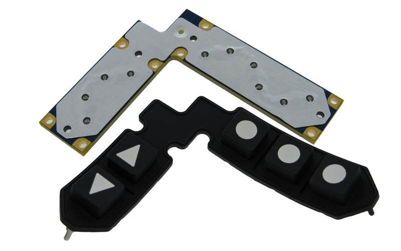 Figure 1: Static shield made of aluminum foil laminated to the outer layer of a dome switch assembly.
Metallized Foil Shield
Made from a metallized Mylar foil, these shields are effectively thin plastic layers of material with a thin conductive film deposited on one surface (Figure 2). Similar to the foil within a shielded cable, this metallized foil acts as a thinner version of the static shield above. Metallized foil shields are our most common shield technology. These are most common in membrane switch assemblies as a low-cost and ultra-thin profile way to improve the keypad shielding.
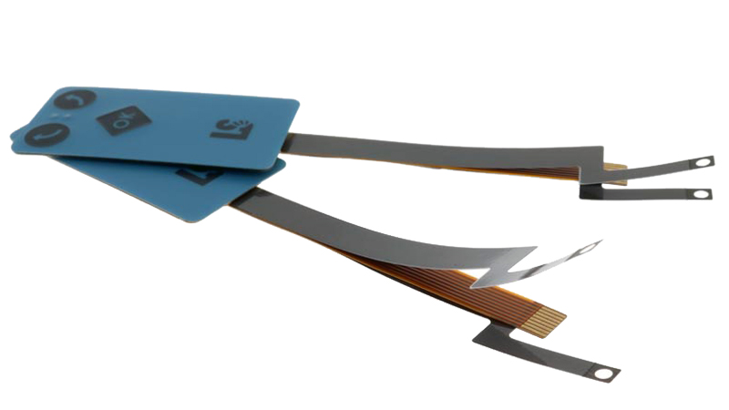 Figure 2: A thin conductive coating on Mylar film provides shielding in membrane switch assemblies where space is limited.
Printed ESD Shield
For less critical applications, or where low-cost solutions are critical, a screen-printed shield layer may be the best option. These thin layers of PET or FPC have a screen-printed conductive layer formed in a hatched pattern and are used as an ESD shield (Figure 3). These shield layers can be terminated to grounding tabs or connectors to help provide an electrical reference to ground. Customers do not need to specify the shape and width of the cross-hatched pattern; instead, Epec will develop this design.
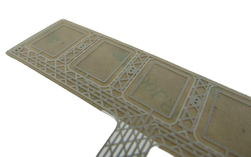 Figure 3: A screen-printed conductive crosshatch on a flexible substrate forms a thin ESD shield that can be grounded through a tab or connector.
EMI Paint for Enclosures
Injection molded enclosures and front panels are among the most common housing types for HMIs, keypads, and other user interface devices. For these types of products, shielding the buttons or keypad alone may be insufficient, leaving the entire enclosure acting as an improperly designed Faraday cage- potentially radiating noise to the surroundings. Instead, electrically conductive paints and coatings can be applied to the interior surfaces of the injection-molded housing (Figure 4) to provide an electrically shielded enclosure.
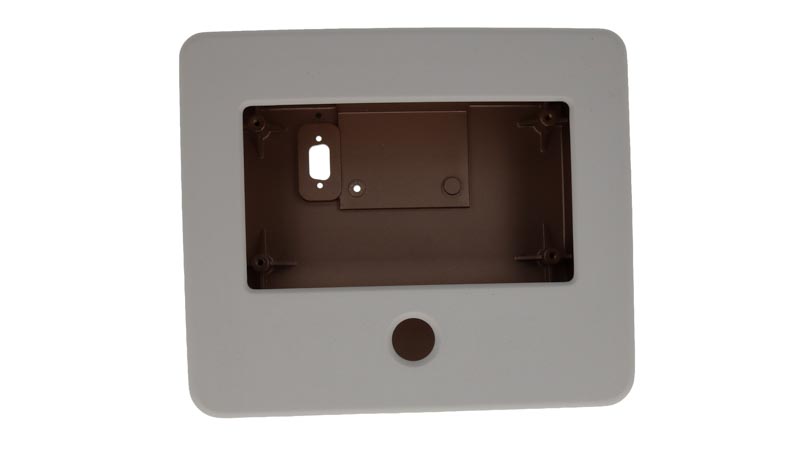 Figure 4: Conductive paint added to the inside of a PC/ABS injection-molded housing.
Control ESD Current at the Entry Point
ESD protection should begin by identifying accessible discharge locations. These may include a metal bezel, mounting screw, connector shell, exposed conductive feature, or gap near an overlay edge. The preferred current path should carry the disturbance toward the intended chassis or referenced ground without forcing it through sensitive circuitry.
TVS (transient voltage suppressor) devices can be used to protect signal lines and should be placed near the ESD entry point. TVS selection should consider working voltage, clamping behavior at the relevant pulse current, capacitance, leakage, polarity, and pulse capability.
An ESD protection rating also does not establish suitability for every other transient. Electrical fast transients and surge events have different waveforms and energy demands, which may require a different protection network. Electrical testing is recommended early in the project to review the impact and resilience of protection components.
Filter Membrane Switch Inputs Without Disrupting Scanning
A membrane switch matrix often connects controller inputs to relatively long conductors through a flexible tail. These conductors can couple interference into the input circuitry, particularly when the receiving nodes have high impedance.
The actual response depends on driver impedance, pull-up resistance, switch resistance, parasitic capacitance, and the controller’s input thresholds. Verify that each row or column settles before sampling under worst-case tolerances. Excessive filtering can create delayed transitions or incorrect key detection.
Firmware debounce should address mechanical contact behavior and brief input instability. It should not be expected to prevent electrical overstress or compensate for an uncontrolled discharge path.
Treat Capacitive Touch as a Separate EMC Problem
Capacitive sensing depends on detecting a small change in capacitance against a larger baseline. Shield placement, overlay construction, nearby metal, and interference therefore affect both sensitivity and immunity.
A grounded shield can reduce coupling from surrounding circuitry, but it also adds capacitive loading. Sensor routing should remain separated from display clocks, switching nodes, and backlight conductors. Evaluate raw sensor counts, baseline movement, and noise margin in the final mechanical stack rather than relying solely on correct button operation.
Controller filtering, acquisition settings, and supported frequency-management features can improve noise tolerance. Evaluate these settings alongside touch response time, since stronger filtering may delay recognition of an intentional input.
Validate the Complete HMI Under Active Operation
A proposed validation plan should exercise the assembly in its intended enclosure with representative cables, grounding, power supply, firmware, and connected equipment. Testing an isolated switch or controller board cannot establish the behavior of the complete interface.
Exercise operating modes that change switching activity, including display updates, communication traffic, backlight dimming, and simultaneous key scanning. For touch systems, include active touches as well as idle operation.
Monitor more than visible resets. Record unintended commands, missed inputs, communication errors, display faults, and changes to stored settings. Where practical, capture controller reset causes and diagnostic data so a temporary disturbance can be distinguished from a persistent hardware fault.
Summary
Effective EMC and ESD protection for an HMI depends on coordinated control of current paths throughout the assembly. Shield coverage, low-inductance bonds, protection placement, continuous signal references, and correctly timed input filtering must work together.
Membrane switches and capacitive touch systems also require different treatment because their sensing mechanisms respond differently to added capacitance and interference. Defining functional acceptance criteria early, then validating the complete operating assembly, provides a stronger basis for reliable performance than selecting protective components in isolation.
Experiencing EMC or ESD Challenges with Your HMI Design?
EMI interference and electrostatic discharge can lead to unexpected performance issues with your user interface. Epec's engineering team can review your design, recommend shielding options, and help address potential EMC and ESD concerns before they impact production.
Request a Quote Request Design Support