


Continuity Testing: Validating Reliability in Custom Cable Assemblies By Steven J. Goodman, User Interface & Cable Assembly Product Manager Epec Engineered Technologies
In custom cable assembly manufacturing, testing is often viewed as the final checkpoint before shipment. However, for high-reliability applications in medical, aerospace, industrial, and defense systems, testing is far more than a pass/fail exercise. A well-developed testing strategy validates electrical integrity, confirms workmanship quality, and helps identify defects before assemblies reach the field.
Many cable assemblies will successfully pass a basic continuity test while still containing latent reliability issues that can lead to intermittent failures, insulation breakdowns, or signal degradation during operation. As cable designs become more compact and electrically complex, especially in multiconductor cables where multiple conductors, terminations, and insulation paths must be verified, manufacturers must adopt broader testing methodologies that evaluate both the electrical and mechanical performance of the finished assembly (Figure 1).
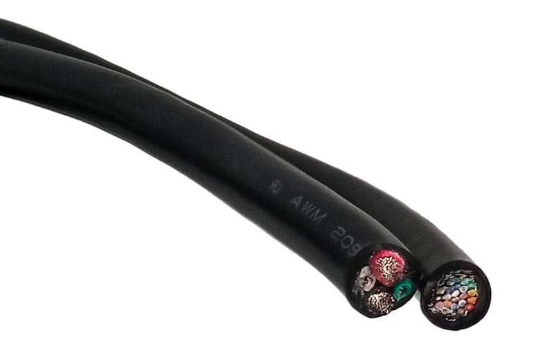 Figure 1: Electrical testing is critical for multiconductor cables.
Why Cable Assembly Testing Matters
Custom cable assemblies operate in environments where failure is often unacceptable. Applications involving medical devices, military electronics, robotics, automation systems, and high-speed communications require assemblies that can maintain stable electrical performance under repeated movement, thermal cycling, vibration, and environmental exposure.
At its most basic level, cable testing verifies that the assembly was built correctly. Continuity testing confirms that conductors are connected from point A to point B without open circuits or incorrect pin assignments. While this is a foundational requirement, continuity alone does not guarantee long-term reliability.
A cable assembly may pass initial continuity testing while still containing:
- Weak crimps
- Damaged insulation or wire strands
- Intermittent shorts
- High-resistance connections
- Improper shielding termination
- Connector misalignment
- Corrosion or other contamination
- Mechanical strain points
These issues may not become apparent until the assembly is installed and exposed to real-world operating conditions.
Continuity Testing as the Baseline
Continuity testing remains one of the most common and important electrical tests performed on cable assemblies. Epec follows a strict standard of 100% continuity testing on all cable assemblies and wire harnesses.
For simple assemblies, continuity testing may be performed manually using a multimeter or handheld test devices (figure 2). More complex wire harnesses and multi-conductor assemblies typically require automated test systems capable of verifying dozens or hundreds of connections quickly and accurately.
As the complexity of harnesses increases, or designs that employ specialty or industry-specific connectors, custom interface cables and breakout PCBAs may be needed to properly test the design. Many of today's high-end electrical test equipment is designed using high-density multiconductor cables and connectors that cannot mate with any ordinary cable; instead, it will require an interface connection to be designed and built.
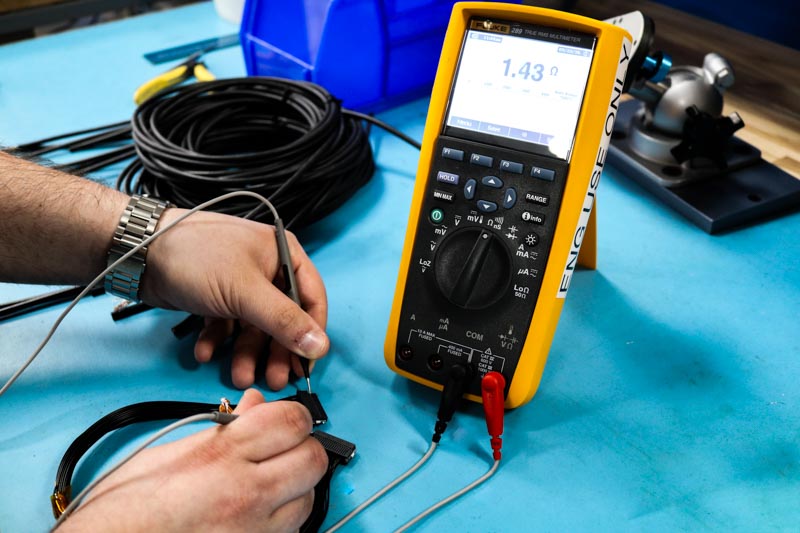 Figure 2: Manual continuity testing with a multimeter can confirm basic electrical paths in simple cable assemblies before more advanced testing methods are required.
In high-volume manufacturing environments, automated continuity testing also improves repeatability while reducing operator error. In-process testing can be done before an overmold is added, shrink boots are installed, or potting compound is sealed.
However, continuity testing only validates whether a connection exists. It does not evaluate insulation integrity, dielectric strength, or long-term reliability under electrical stress.
The Role of HiPot and Insulation Testing
High-potential testing, commonly referred to as HiPot testing or DWV (dielectric withstanding voltage), evaluates the insulation performance of a cable assembly by applying elevated voltage between conductors or between conductors and ground.
Unlike continuity testing, which confirms that electrical paths are connected correctly, HiPot testing verifies that conductive paths remain properly isolated from one another. This is especially important in assemblies carrying higher voltages or operating in safety-critical environments.
HiPot testing can reveal:
- Insulation damage
- Pinched conductors
- Contamination
- Inadequate spacing
- Poor solder cup workmanship
- Weak dielectric materials
- Leakage current issues
In many industries, HiPot testing is required to comply with safety standards and qualification requirements. The test parameters, including voltage level, ramp rate, dwell time, and allowable leakage current, are typically defined by customer specifications or industry standards.
For complex cable harnesses with high conductor counts, automated switching systems are often integrated into test platforms to validate multiple conductor combinations efficiently.
Milliohm and Resistance Testing
Resistance testing is another critical component of cable assembly validation, particularly for power distribution and low-voltage signal applications. Milliohm testing measures the resistance of conductors, crimps, solder joints, and termination points to identify high-resistance connections that may not appear during basic continuity checks.
Even small increases in resistance can generate heat, voltage drop, or unstable signal transmission during operation.
High-resistance conditions are often caused by:
- Poor crimps
- Cold solder joints
- Damaged conductors
- Improper plating
- Connector contamination
By establishing acceptable resistance thresholds, manufacturers can detect subtle process issues before assemblies leave production.
Mechanical and Environmental Validation
Electrical testing alone does not fully validate a cable assembly’s reliability. Many field failures originate from mechanical stress rather than electrical design flaws.
Repeated bending, torsion, vibration, and pull force can gradually weaken conductor strands or connector terminations over time. This is especially true in dynamic applications such as robotics, wearable medical devices, aerospace systems, and industrial automation equipment.
Mechanical validation may include:
- Flex testing
- Pull testing
- Bend radius verification
- Connector retention testing
- Vibration testing
- Strain relief validation
Environmental testing may also be required depending on the application. Exposure to heat, cold, humidity, fluids, UV radiation, or chemicals can degrade insulation materials and compromise assembly performance.
For high-reliability programs, testing often extends beyond production validation into qualification and lifecycle simulation to ensure the cable assembly can withstand real-world operating conditions.
The Importance of Custom Test Fixtures
As cable assemblies become more specialized, standard test equipment is often not enough. Many custom assemblies require dedicated fixtures designed specifically for the connector configuration, pin layout, and electrical requirements of the product.
Custom fixtures improve:
- Testing accuracy
- Repeatability
- Throughput
- Operator efficiency
- Connector protection during repeated testing
This becomes especially important for complex circular connectors, fine-pitch interfaces, RF assemblies, and hybrid cable systems that combine power, signal, and high-speed data transmission within a single assembly.
In many cases, fixture development must occur alongside product development to ensure production testing can support manufacturing volume requirements.
Building Reliability into the Manufacturing Process
The most effective cable assembly testing strategies begin long before final inspection. Reliable manufacturing requires process control at every stage, including material selection, crimp validation, soldering processes, overmolding, shielding termination, and assembly handling.
Testing should not be viewed to “catch defects” after production. Instead, it should function as part of a broader quality system designed to prevent defects from occurring in the first place.
Summary
At Epec Engineered Technologies, testing methodologies are developed around the specific electrical, mechanical, and environmental requirements of each application. Depending on the design, this may include continuity testing, HiPot testing, resistance measurements, mechanical validation, custom fixture development, and application-specific inspection criteria.
As cable assemblies continue to evolve toward smaller geometries, higher speeds, and greater complexity, comprehensive testing becomes increasingly important. Manufacturers that rely solely on basic continuity checks risk overlooking issues that may only appear after deployment.
For critical applications, reliability is not validated by a single test. It is achieved through a combination of engineering, process control, and a testing strategy designed specifically for the assembly’s intended operating environment.
Looking For a Custom Cable Assembly?
Our team of engineers can help you to select the proper materials and components that are best suited to exceed your application requirements. From design to production, we are here to help you get the right cable for your application.
Request a Quote Request Design Support