Battery Pack Configurations
Battery pack configurations can be designed with several options, some of which are determined by the chemistry, cell type, desired voltage and capacity, and dimensional space constraints. The basic explanation is how the battery cells are physically connected in series and parallel to achieve the desired power of the pack.
Check out this design guide, Custom Battery Pack Design Guide - Manufacturing Capabilities.
The physical layout of the configurations is typically designed to fit within a desired dimensional space. Pure nickel buss material (and spot welding to assemble) is the most common interconnect method. However, when a design requires high pack amperage, the buss material becomes another critical factor for the design. Learn more about how to select your battery pack cell type.
There are an infinite variety of battery pack combinations. Below we have outlined the most popular for cylindrical cells.
Linear or F Type
Note that the straps will both come off the top when there are an even number of cells, and one off the top, the other off the bottom when there is an odd number of cells..

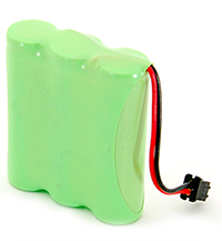
With a connector and heat shrink wrap they look like this:
Multi-Row Cells
There are two ways to start packing them. One could be called the cubic, and the other face centered cubic, or nested.
Cubic packing is in neat rows. The size of such a pack is nD x mD x H, where n is the number of cells in a row, m is the number of rows, D is the cell diameter, and H is the cell height.

Another example of cubic or composite F Type configured in multiple rows

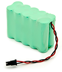
Photo of completed multiple row configured cells battery pack below:
Nested Type Cells
Nested configurations follow the same connection principles using the same nickel tab material to achieve the design. This type of configuration is typically supported with outer shrink wrap to give the cells additional support. The exposed ends of the cells are typically protected with fish paper.
Some nested deigns are even potted to support the cells and protect the completed battery for overall integrity.
Either method is acceptable and should be considered for best handling practices and protection for the battery during transit.

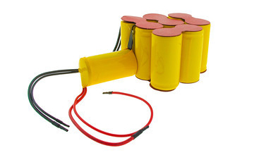
Photo of custom nested cell pack below:
Face centered Cubic

Face centered cubic packing is nested to take up less room. Calculating the size takes a little geometry.

Circular Type Cells
Circular configurations are common and used in many applications. Again, following the same tab welding principles, can be stacked for more capacity, and typically shrink wrapped to support the cells.
For a 3-cell pack, you can put the cells in a tube:

For a four-cell pack in a circular tube:

The diameter of the circumscribing circle is 2.41 D.
For example, with AA cells the diameter is 14.2 mm, so three would fit into a tube 30.7 mm in diameter, and four would fit in a tube 34.22 mm in diameter. You will want to expand this slightly to account for up to 0.5 mm variation in cell diameters.
Linear or L-Type Cells
Example of a stack of cells configured end to end below:

These are typically constructed by standing two cells side by side and welding a nickel strip across the terminals. The cells are configured end-to-end by bending the nickel strip in a "U" shape. Overall pack dimensions will need to allow a thickness increase of 1/2 to 1 mm per junction for this to accommodate the folded nickel tab.
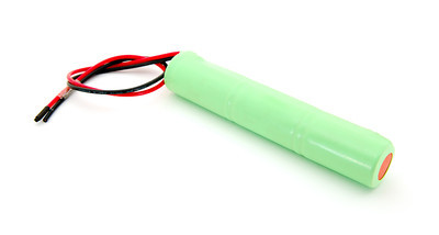
Photo of completed linear configured battery pack below:
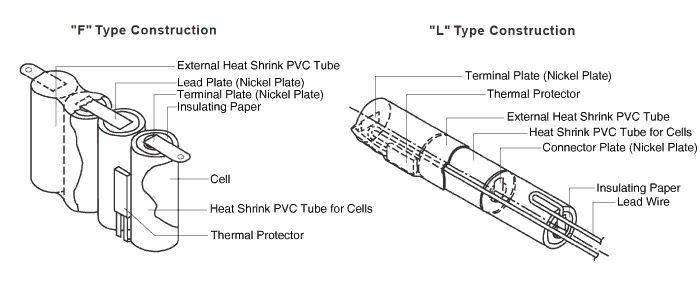
Some construction views to show how the battery packs are fully assembled
Unsure Of the Battery Configuration You Need?
Optimize your energy solutions with our custom-configured battery packs. From linear to circular configurations, our design team can help you meet your specific needs.
Request a Quote Request Design Support Request More Information


