Metal Clad and Heat Sink Printed Circuit Boards
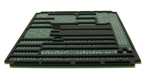
Epec has over 30 years of experience in manufacturing metal clad PCB, metal core PCB (MCPCB), and PCBs with an external heat sink attached. These technologies create unique design and manufacturing challenges that go well beyond a typical printed circuit board.
Listed below you’ll find all the different MCPCB technologies that we provide. Working with an experienced, knowledgeable PCB manufacturer is highly recommended to ensure your MCPCB requirements are not only buildable but cost effective as well.
Single Sided Metal Clad PCBs
Single sided is the most common and cost-effective metal clad PCB, mainly used in high volume applications such as LED lighting, automotive lighting, and other consumer products. Even the most common MCPCB technology still requires specific equipment and know-how for manufacturers to design and build it correctly. See our page on Aluminum printed circuit boards for more information.
Metal Core or Double Sided Plated Through Hole Metal PCBs
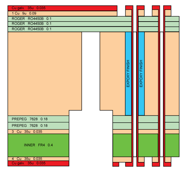
Metal Core or double sided plated through hole PCBs combine traditional PCB materials (FR4 or Teflon typically) separated by an internal layer of metal (typically copper or aluminum). An example of a stack-up for one of these types of products is below.

We use our lamination press to laminate dielectric layers to a metal core. Many times, the inner layers require circuitry prior to laminations while other times we are creating outer layers that require further processing. For high technology projects in the aerospace and defense industries there can even be multiple lamination cycles to manage blind and buried via applications.
The benefits of using MCPCB technology for your design to improve thermal conductivity and thermal stability are clear. However, this technology comes with some manufacturing challenges that should be considered prior to starting.
Benefits of Metal Core PCB
Thermal Conductivity
With today’s high-speed PCB requirements, many materials have low Dk and low loss properties but lack any of the thermal properties required to make their application function at its optimal level. Traditionally, we would attempt to add copper weight to the layers of a multilayer PCB, which adds significant cost to the PCB. This would also require multiple mechanical interconnects between layers, which are susceptible to failure over the life of a PCB.
With a metal core board, we can minimize the number of interconnects necessary along with providing multiple plated through hole (PTH) opportunities for the customer to connect with the internal metal core to help dissipate the heat evenly.
Thermal Stability
One of the biggest challenges a designer faces when developing technology with multiple different materials is making sure they take into consideration the different characteristics of each material, including thermal compatibility.
When it comes to PCBs, the most important variable to account for is CTE (Co-efficient of Thermal Expansion) of each of material. It is critical to match materials with correct Z-Axis CTE values so that you can minimize the expansion of the material in operation, which can cause de-lamination or hole-wall separation in the metal core PCB.
Overall PCB Rigidity
In many PCB applications, the ability to survive shock and vibration is key to long-term reliability of our end product. Using copper, aluminum, and even carbon composites allows us to make the PCB much more rigid to the point where we can make the PCB 2-4 times stiffer than straight FR-4 or polyimide designs.
Metal Core PCB Challenges
Below are some of the critical challenges that a fabricator will face when manufacturing metal core PCBs. These are the most consistently documented issues over years of experience affecting the ability to efficiently and cost effectively produce MCPCB.
Plated Through Holes
One of the biggest challenges when manufacturing metals core PCBs (or any printed circuit boards really) is making sure you can prepare the hole wall properly, removing all the debris from drilling to assure that a reliable hole wall call be deposited.
For example, in the drawing above you have Teflon from the Rogers material, resin from the FR-4, and copper fragments from the copper all stuck to the hole wall after drilling. Traditional de-smear techniques and processes will not work here, which is why it is critical to use Plasma Desmear for these types of boards and to have a coupon on the production panel which can be cross sectioned to ensure hole wall cleanliness prior to electroless copper (which is the only metal deposition technique that will work here) as there is no turning back from that step.
Assuring That the Thermal Expansion Properties of the Materials Are Similar
As discussed above, it is critical to understand the operating CTE temperatures for reliable operation of metal core PCBs. For the manufacturer, it is just as important to understand the CTE parameters when developing processes like lamination cycles and HASL. Many times, we will strategically place thieving into our production panels to draw heat away from the production parts.
Extremely Tight Tolerances
Traditional PCB tolerances of +/- 0.005” or +/- 10% for many of the mechanical and electrical properties don’t always apply to MCPCB. When trying to attach a high speed to a metal core PCB to do two functions in one, we get into very tight electrical tolerances that can be down to +/- 0.001”. With those tight tolerances, many of the mechanical dimensions require precision CNC machining when it comes to routing to and through metal cores.
Heat Sink PCB
Before the technology existed to use metal materials as a PCB core, the most cost-effective method was to fabricate a separate metal heat sink. That separate heat sink would then be registered to a finished PCB and attached using liquid adhesive or traditional pre-preg in a lamination press under heat and pressure.

This method is still quite common today, as it is still the most cost effective and the number of materials you can make heat sinks from and use to attach have dramatically changed.
Materials Typically Used for Heatsinks:
- Aluminum Alloys
- Copper
- Brass
- Steel
- Composite Materials
- Bronze
Materials Used to Attach Heat Sinks:
- Pyralux
- Ablefilm
- Thermabond
- Cybond
- Nitro Phenolic
- Kapton
- No-Flow Prepregs
- Flowable Adhesives
Many of these come in sheet form where they must be CNC pre-formed to the heat sink shape prior to lamination which requires scaling, as not every material acts the same.
Expertise In MCPCB Technologies
Ready to elevate your thermal performance and long-term reliability in PCB design? Navigate the complexities of metal core PCBs with a partner who ensures your design is not only buildable but cost-effective.
Request a Quote Request Design Support Request More Information


