Flex Circuit Stiffeners
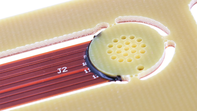
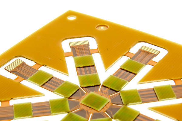
In flex circuits and rigidflex PCBs, stiffeners are a common requirement for many designs because they improve overall durability and reliability. Their role is mechanical rather than electrical, supporting the flexible area where added rigidity is needed. Depending on whether stiffeners are required on one or both sides of the flex, additional lamination cycles may be necessary, which can increase both cost and lead time. Despite these tradeoffs, certain applications make stiffeners an essential design element.
Stiffeners are typically added as one of the final fabrication steps. They can be attached using either pressure-sensitive adhesive (PSA) or thermalset adhesive, depending on performance requirements and cost considerations.
Here are the Top 5 Reasons for Using Stiffeners on Flexible PCBs.
At a Glance: Flex Circuit Stiffeners
- Flex circuit stiffeners are a common mechanical requirement in many flex and rigidflex PCB designs.
- Stiffeners improve durability and reliability by adding localized rigidity without contributing to electrical performance.
- Their use can impact cost and lead time, making proper specification and fabrication planning important.
Why Use Stiffeners in Flex Circuit Applications
Flexible PCB stiffeners are used to address specific mechanical and assembly challenges. They are commonly applied to reinforce areas exposed to repeated mechanical stress or to meet connector interface requirements.
Common Reasons for Using Flex Circuit Stiffeners
- Rigidizing connector areas to relieve stress from larger connectors or repeated insertions
- Meeting ZIF (Zero Insertion Force) connector thickness requirements
- Creating localized bend constraints
- Providing flat surfaces for SMT pads and components
- Minimizing stress on solder joints and components
- Managing heat dissipation when using metal stiffeners
- Rigidizing arrays for automated assembly without fixtures
For more information see our blog post on the purpose of a flex circuit stiffener.
Things to Know About Flex PCB Stiffeners
From a cost perspective, PSA attachment is often slightly less expensive than thermalset adhesive. Thermalset adhesive, typically traditional PCB prepreg, requires the flex PCB to return to the lamination press for heat and pressure curing. The adhesive must also be precut to match the stiffener shape, adding process complexity.
When stiffeners are used with platedthroughhole components, they must be placed on the same side of the board where components are inserted to allow access to solder pads. Accurate registration between stiffener holes and platedthrough holes is critical to ensure proper component insertion. Close collaboration with the flex PCB fabricator is required to confirm that the adhesive system and registration method meet design objectives.
Find out Why Flexible Circuit Boards Need Stiffeners.
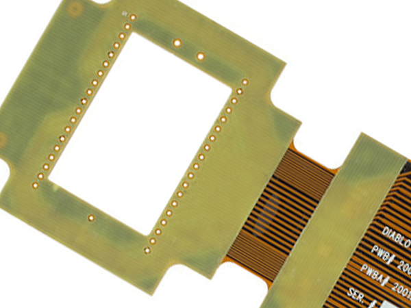
Component / Connector Stiffeners
Function:
- Create localized rigid areas where components or connectors are attached
- Prevent flexing in component areas to protect solder joints
Material Options:
- FR4, Polyimide, Aluminum, Stainless steel
- Available in a variety of thicknesses
Attachment Methods:
- Thermally bonded with flex adhesive
- Pressure Sensitive Adhesive (PSA)
ZIF Stiffeners
Function:
- Increase localized thickness at contact fingers to meet specific ZIF connector requirements
Material Options:
- Polyimide only
- Available in a range of thicknesses to meet design requirements
Attachment Methods:
- Thermally bonded with flex adhesive only
Localized Bend Constraints
Function:
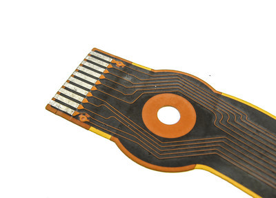
- Restrict bend areas to specific locations
- Support final assembly, defined bend requirements, or enduse needs
Material Options:
- FR4, Polyimide
Attachment Methods:
- Thermally bonded with flex adhesive
- Pressure Sensitive Adhesive (PSA)
Click here to view Various Stiffener Materials for Flexible Circuit Boards.
Design Tips for Cost and Reliability
Adding stiffeners increases processing time, materials, and labor, which adds cost, so special care should be taken to only add when necessary. To reduce stress points, stiffener and coverlay termination points on top and bottom layers should overlap by a minimum of 0.030 inches. Keeping all stiffeners the same thickness can also help reduce fabrication time and cost.
For thickness selection, choosing common laminate thicknesses such as 0.010, 0.031, 0.047, or 0.062 inches can help minimize cost and lead time. Each fabricator maintains its own material inventory, so working closely with the manufacturer helps avoid specifying uncommon thicknesses that create logistical challenges.
Typical Stiffener Thickness and Design Parameters
| Parameter | Value | Units |
|---|---|---|
| Common stiffener thicknesses | 0.010 / 0.031 / 0.047 / 0.062 | inches |
| Minimum overlap at termination points | 0.030 | inches |
How Automated Stiffener Placement Enhances Flex Circuit Reliability
Many manufacturers also support automated machines for placing stiffeners rather than manual placement for certain cases. Automated stiffener placement supports consistent registration and repeatability during fabrication.
This approach improves alignment accuracy, reduces manual handling, and helps maintain reliability when stiffeners are required in highvolume or complex flex circuit designs.
Maximize Durability and Efficiency
Selecting the right stiffener materials, thicknesses, and attachment methods is essential to achieving reliable flex circuit performance without unnecessary cost or leadtime impact. Working with experienced flex PCB manufacturers ensures stiffeners are properly specified and integrated into the overall design.
Watch Our Video
How Automated Stiffener Placement Enhances Flex Circuit Reliability
Frequently Asked Questions
Quick Links
- What is the primary purpose of a flex circuit stiffener?
- Are stiffeners part of the electrical function of a flex circuit?
- When are multiple lamination cycles required?
- What attachment methods are used for flex PCB stiffeners?
- Why is registration important for component stiffeners?
- What materials are commonly used for flex circuit stiffeners?
What is the primary purpose of a flex circuit stiffener?
A flex circuit stiffener provides mechanical support to improve durability and reliability in specific areas of a flex or rigidflex PCB.
Are stiffeners part of the electrical function of a flex circuit?
No. Stiffeners serve a mechanical role only and are not part of the electrical requirements of the circuit.
When are multiple lamination cycles required?
Multiple lamination cycles may be needed when stiffeners are applied to one or both sides of the flex circuit.
What attachment methods are used for flex PCB stiffeners?
Stiffeners are attached using either pressuresensitive adhesive or thermalset adhesive, depending on design and cost needs.
Why is registration important for component stiffeners?
Accurate registration ensures stiffener holes align with platedthrough holes so component leads can be inserted correctly.
What materials are commonly used for flex circuit stiffeners?
Common materials include FR4, polyimide, aluminum, and stainless steel, depending on the application and function.
Maximize Durability and Efficiency
Get expert advice on the right stiffeners for your Flex Circuit needs. Don't compromise on performance or lead time. Reach out for a consultation today.
Request a Quote Request Design Support Request More Information


