


RF Coaxial Cables
High frequency electrical signals, commonly referred to as Radio Frequency (RF), are used in a variety of applications including everything from cable television to Wi-Fi, to cellular phones, to medical imaging devices. RF signals cover waveform frequencies of 3kHz to 300GHz, which cannot be transmitted through conventional stranded copper cables. Instead, RF cables are designed to handle ultra-high frequency conditions through a combination of specialty materials and construction techniques.
RF coaxial cables are constructed with a center conductor, dielectric, and outer conductor to transmit signals with minimal interference and signal loss. Their shielded design controls RFI/EMI and maintains stable impedance, making them well suited for RF and microwave applications. Proper selection of electrical and mechanical parameters is critical to maintaining performance.
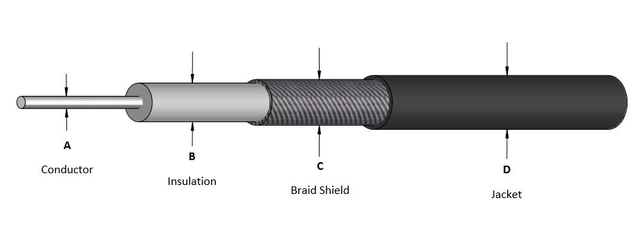
RF coaxial cable assemblies are designed using dielectric materials such as PTFE and Teflon to transmit electrical signals with controlled impedance and minimal signal degradation. The fundamental structure consists of a center conductor made of copper, an insulating dielectric, and an outer conductor like a braid or foil that provides shielding.
Coaxial cables are engineered to confine electromagnetic fields within the cable geometry. This minimizes both signal leakage and susceptibility to external interference, making them a reliable solution for environments where signal integrity is critical. Critical performance characteristics include properties such as insertion loss, VSWR, frequency range, impedance, and maintaining proper bend radius.
RF cables can be expensive. They are on average more expensive than traditional copper cables. They are more expensive to build, more expensive to test, and require far more sophisticated equipment to be electrically tested.
At a Glance: RF Coaxial Cables
- Designed for high-frequency signal transmission (3 kHz to 300 GHz) with controlled impedance and minimal loss.
- Shielded coaxial construction (center conductor, dielectric, outer conductor) confines electromagnetic fields and reduces RFI/EMI interference.
- Critical performance factors include insertion loss, VSWR, frequency range, impedance, shielding effectiveness, and bend radius.
Coaxial Cable Structure
A coaxial cable includes three primary elements that define its electrical and mechanical performance:
- Center conductor: Typically, a solid copper wire used to carry the electrical signal
- Dielectric (insulating spacer): Separates the inner and outer conductors and maintains consistent spacing
- Outer conductor (shield): Usually a braided or foil metal layer that contains electromagnetic fields
An additional outer jacket is often applied to protect the cable from environmental exposure and insulate the bundle. This outer jacket is usually extruded thermoplastic or wrapped with insulating tapes and films.
RF Coaxial Cable Applications
Coaxial cables are primarily used for transmitting radio frequency energy in applications where impedance control and interference management are required.
They are commonly used in:
- Frequency ranges of 3kHz to 300GHz
- RF and microwave systems
- 50-ohm and 75-ohm signal transmission environments
- Applications sensitive to RFI/EMI interference
- Systems requiring electrical stability, including military and aerospace applications
These environments demand consistent signal performance where both signal loss and interference can negatively impact overall system operation.
Key Electrical Performance Parameters
When specifying an RF coaxial cable assembly, several performance characteristics must be evaluated to ensure proper operation.
Insertion Loss
Insertion loss is measured in decibels (dB) and represents signal loss as it travels through the cable. Loss increases as frequency increases, making it a key parameter in high-frequency applications.
Voltage Standing Wave Ratio (VSWR)
VSWR, sometimes pronounced as “vishwa”, indicates how efficiently RF energy is transmitted from the source through the cable to the load. Higher values indicate reduced efficiency, and VSWR typically increases with frequency.
Frequency
Frequency is measured in Hertz (Hz) and represents the number of signal cycles per second of the waveform. RF and microwave ranges include:
- High Frequency (HF): 3–30 MHz
- Ultra-High Frequency (UHF): 0.3–3 GHz
- Super High Frequency (SHF): 3–30 GHz
- Extremely High Frequency (EHF): 30–300 GHz
Impedance
Impedance, measured in ohms, defines resistance to current flow and must be controlled to match system requirements. Common RF systems utilize 50-ohm or 75-ohm configurations.
Materials and Construction Considerations
Dielectric Materials
The dielectric is a critical element that controls spacing between conductors and impacts electrical performance.
Common dielectric materials include:
- Air
- PTFE (Polytetrafluoroethylene)
- ETFE (Ethylenetetrafluoroethylene)
- FEP (Fluorethylenepropylene)
These materials are selected based on electrical and environmental requirements.
Shielding
Shielding is provided by foil, braid, or a combination of both and serves as the conductive barrier that contains electromagnetic fields.
Shielding effectiveness is influenced by:
- Conductor diameter
- Required flexibility or bend radius
- Electrical performance requirements
- The type of shielding and materials used
Bend Radius and Mechanical Performance
Bend radius defines the minimum allowable curvature without degrading cable performance. It is measured along the inside of the bend.
Exceeding the specified bend radius can result in:
- Stretching of the dielectric
- Misalignment of the center conductor
- Changes in impedance
These effects can lead to increased VSWR and higher insertion loss, directly impacting signal integrity.
Frequently Asked Questions
Quick Links
- What is RF coax?
- What should I know about coaxial cable structure?
- Why is shielding important in coaxial cables?
- What affects coaxial cable performance?
- What happens if bend radius is exceeded?
What is RF coax?
RF coax is a type of coaxial cable designed to transmit radio frequency signals with controlled impedance and minimal interference through a shielded structure.
What should I know about coaxial cable structure?
A coaxial cable consists of a center conductor, dielectric, and outer shield. This configuration confines electromagnetic fields and reduces both signal loss and external interference.
Why is shielding important in coaxial cables?
Shielding prevents external electrical and magnetic fields from interfering with internal signals and limits signal radiation from the cable itself.
What affects coaxial cable performance?
Key factors include insertion loss, VSWR, frequency, impedance, dielectric properties, shielding effectiveness, and bend radius.
What happens if bend radius is exceeded?
Exceeding bend limits can distort the cable structure, causing impedance changes, increased VSWR, and higher signal loss.
Looking For an RF Coaxial Cable Solution?
Our engineers are here to help you with every aspect of your RF coaxial cable. From design to production, we can help you get the correct solution for your application.
Request a Quote Request Design Support Request More InformationRequest a FREE Quote!
We are here to help create a cable assembly that will exceed your requirements.
Get Your Quote Now! Not Ready for a Quote? Request more info or email us your inquiry.