Gerber Layout & Design Recommendations
Epec's engineering team offers full flex and rigid-flex circuit design services. During our application review and quoting process, we carefully examined specifications, materials and construction in order to minimize and eliminate any technical issues.
We also look for areas of opportunity for improving the design of your flex or rigid-flex circuit's reliability, functionality, and ensure there are no IPC design standard violations. Cost reductions are also identified to generate an accurate quote that is based on a manufacturable, reliable and cost effective design.
Radiused Corners within Flex Bend Areas
Having a radiused corner within and flex bend area reduces / eliminates stress concentrators and improves reliability. For a more in-depth look, see our blog post on flex and rigid-flex bend capabilities.

Preferred
Acceptable
Not Allowed
Staggered Layer to Layer Trace Positioning
Staggering your designs layer to layer trace positioning eliminates the "I-Beam" effect which improves the flexibility and reliability of your flex circuit.

Preferred
Not Recommended
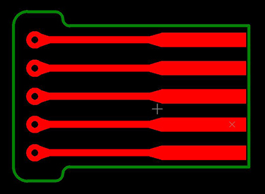
Fillets & Teardrops
Proper fillets and teardrops eliminate stress concentrations and improves the reliability of the flexible PCB.
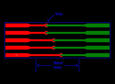
Vias within Bend Areas
This is not recommended. Having vias within a bend area can cause a significant stress concentrator which may lead to breakage.
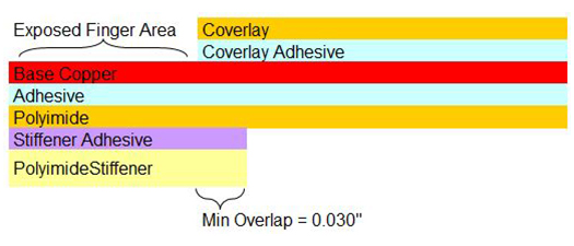
Stiffener & Coverlay Terminations
Proper stiffener and coverlay terminations prevents creation of significant stress concentrator within the flexible circuit board. See our blog post on flex circuit polyimide coverlay and soldermask considerations for more information.
Required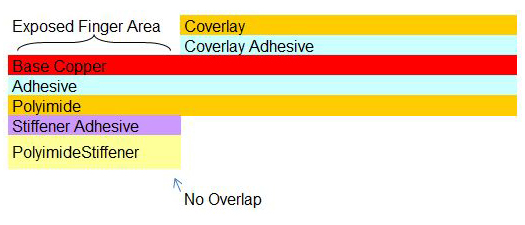
Not Allowed
Looking For Design Help?
Maximize your flex circuit's potential with Epec's engineering team. We focus on enhancing reliability and reducing costs. Get your custom quote now for a robust design solution.
Request a Quote Request Design Support Request More Information

