HMI Backlighting Options for Maximum Performance
By Paul Knupke - Epec Engineered Technologies
Product designers and industrial designers can struggle with specifying backlighting options for custom HMI (Human-Machine Interface) products. Backlighting techniques can be counterintuitive and often at odds with other elements of the user interface design.
For this article, custom user interface keypads, or simply HMI's, are defined as custom assemblies with arrays of logic-level switches, graphics and other electro-mechanical components used in OEM (Original Equipment Manufacturer) applications. The user interface is a component assembly supplied to the OEM and is critical to the OEM's end application.
Examples of user interface end applications include medical electronics, test equipment, communication electronics, military electronics and process control equipment. The aesthetics of the custom user interface design blends with the visual and industrial design of the end application. In other words, the user interface part of the application appears to be integral to the external visual features and design of the end application rather than simply "stuck on" the front of the end application. User interfaces are low profile – less than a 1/2 inch thick.
Besides the graphics and array of switches associated with the HMI, an OEM designer often needs to add some form of backlighting to the user interface. Backlighting assists the end user in operation of the OEM application or improves the intuitive operation of the end application. Design Engineers should be aware of the types of backlighting available and how the backlighting is incorporated before the user interface design begins. This can cause development delays and additional costs when adding backlighting requirements to user interfaces late in the design process. Backlighting is integral to the design, not an option feature such as choosing between leather or cloth seats in a new automobile. Backlighting decisions are similar to deciding a new automobile must seat 7 passengers before considering a sub-compact automobile.
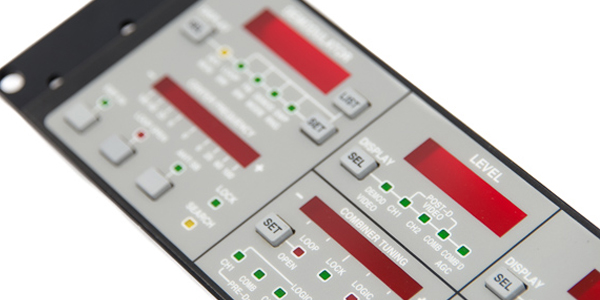
Figure 1: Custom Human-Machine Interface with LED backlighting.
HMI Backlighting Functions
Backlighting falls into three broad categories:
- General backlighting of all user interface graphics or at least switch legends and icons so that the end user can operate the end application in very low ambient lighting.
- Selective, controlled backlighting showing the end application's status such as operation mode or activated feature.
- A combination of general backlighting and selective controlled backlighting.
General backlighting provides enough illumination to the user interface graphics so the end user can operate the end application but without being uncomfortable by looking at very bright illumination. Selective, controlled backlighting needs to be much brighter than general backlighting because the selective backlighting conveys information to the end user. End applications in high ambient light environments require high level selective backlighting to be seen. Combining general backlighting and selective backlighting seems to conflicting. However, the selective backlighting illumination level can be automatically adjusted by sensing the ambient light level to modify the selective backlighting illumination drive level to match low ambient light environments. In high ambient light environments, the selective backlighting is increased for the end user.
Backlighting Technologies
Backlighting is accomplished using three major technologies:
- Discrete LEDs
- Electroluminescent (E/L) Lamps
- Fiber Optic Lamps
Discrete LEDs are small packages with an integrated lens and mounted within or immediately behind the user interface. LEDs are available in single colors such as red, green, yellow, blue and white. Color shades between the primary colors are also available. Some LEDs have two different color semiconductor die mounted in the same package with separate drive connections. The two die can be energized separately emitting two different colors depending on which is energized. Both die can be energized at the same time producing a color that is viewed as a color wavelength between the two individual die. For example, a bi-color LED with red and green die will appear orange when both die are energized. The individual die are still only red and green but the eye sees both colors and averages the colors into orange.
Surface mounted chip LEDs can have a small lens to concentrate emitted light into a narrow beam. Most chip LEDs come with a "lens" with a 120 degree or more beam that offers little beam forming. In either case, when the LED is mounted close to a graphic overlay or other backlighted surface, the emitted beam pattern is very small and produces a visual "hot spot". The "hot spot" is ideal for small status windows on graphic overlays.
For general backlighting a larger area including graphics, text or other features, there is not enough distance from the LED for the beam to spread and backlight the large area. The situation can be helped slightly with a thin diffusion layer with a textured coating or embossed texture, but does not produce the desired even illumination. Using more LEDs to illuminate larger areas helps but still produces bright spots and shadows.
Electroluminescent (E/L) lamps offer advantages for backlighting large areas but are not suitable for selective backlighting such as status indicators. Electroluminescent lamps are very thin and are fabricated on a thin layer of plastic film with a thin transparent and conductive coating of indium tin oxide (ITO) or gold. The conductor material is sputtered onto the plastic film in such a thin layer that light can pass through the conductive layer with very little loss. A light producing phosphor layer is silk screened over the ITO or gold conductor layer in the areas that will be illuminated. The phosphor is encapsulated in micro glass beads. The phosphor areas are over printed with conductive silver polymer to provide the second electrode. The E/L lamp assembly is completed by laminating a plastic film layer over the exposed printed silver electrode as an insulator. The two electrodes are connected to the E/L lamp driver by a flexible tail off the edge of the lamp.
The phosphor is illuminated when an AC voltage is applied between the ITO or gold conductor and the screen printed silver conductor. The lighted surface is through the ITO or gold sputtered plastic film. Available E/L lamp phosphor colors are light red, light green, light yellow, light blue and aviation white. The E/L lamp produces exceptionally even light. Custom E/L lamps can be any size or shape and can include through holes. The electrical characteristics of the E/L lamp mimic a capacitor as there is no direct current path between the two electrodes because the phosphor is encapsulated in glass beads. However, the E/L lamp requires 80 to 120 VAC at 400 to 600 Hz to operate. The E/L lamp is cold to the touch when illuminated.
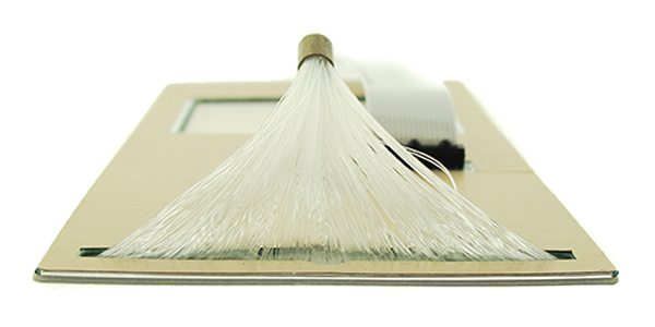
Figure 2: Fiber optic lamp at bundle end and ferrule.
Fiber optic lamps are a woven fabric of thin plastic strands that form a very thin, flat sheet. All of the strands in one axis exit one edge of the flat sheet and are gradually bundled into a tight, round end that is secured with a metal ferrule. The end of the fiber optic bundle is illuminated with a bright lamp. The light travels along the individual plastic strands as the reflective angle of the light is too small escape the strand. When the light reaches the woven part of the flat lamp, or the illuminated area, the radius of the weave creates a larger reflection angle allowing some of the light to escape. The fiber optic lamp is really a misnomer as the plastic strands act as a light pipe, not the light source. The surface of the fiber optic lamp is cool to the touch as the light source is remote from the surface of the lamp.
The fiber optic lamp illumination is very even. Color and brightness is controlled by the light source at the end of the fiber optic bundle. Constraints on light source size are virtually eliminated because the light source is not part of the user interface assembly.
Fiber optic lamps have some significant constraints due to their construction. Through holes in the illuminated portion of the woven fiber optic lamp block light on the opposite side of the through hole from the light source end. There is no light path around the hole. The geometry of the light pipe dictates that the fiber optic lamp width can narrow across the face of the lamp moving away from the light source end but fiber optic lamp width cannot increase across the face of the lamp moving away from the light source.
There is one other type of general backlighting technique that is available but doesn't lend itself to backlighting user interface keypads. That technique uses a plastic panel that is edge lighted with LEDs. Edge lighted panels are used often to backlight liquid crystal displays (LCD). The panel surface is molded or etched with a pattern that redirects the edge light traveling along the plastic panel toward the front of the user interface keypad. The edge lighted panel is not being considered in this article because the plastic panel is not flexible and must be mounted behind the user interface keypad. Various opaque parts of user interfaces prevent shadow free general backlighting.
Human-Machine Interface (HMI) Construction Considerations
Human machine interface keypads include the electrical switch contacts, support means for the electrical switch contacts, interconnecting circuitry, and often electro-magnetic interference (EMI) or electro-static discharge (ESD) shields. All of these elements are opaque to light traveling from the rear to the front of the user interface. Therefore, backlighting must be placed between the opaque elements and the front surface of the user interface. Discrete LEDs, E/L lamp and fiber optic lamp can be accommodated between the electrical switch contacts, shield and circuitry and the front of the user interface.
Another important consideration is the effect of the backlighting technique on the tactile or snap feel of the switch to the end user. If the backlighting technique is an E/L lamp or fiber optic panel, the user's finger pressure on the user interface used to push a switch must flex the E/L or fiber optic panel to close the switch contacts. The resistance to flexing caused by the E/L lamp or fiber optic panel will dampen the tactile fell. Without careful design consideration of all the interrelated elements, the user interface's tactile feel can be completely suppressed. If the OEM designer or industrial designer doesn't fully understand the relationship of all the design elements, they need to work with a user interface manufacturer that understands that the user interface assembly's design is more than a collection of parts.
When discrete status indicator LEDs and/or general backlighting for low ambient light environment are used together, light must be isolated to prevent cross-lighting. In other words, one light area should not be seen visually in another area. There must be a means of blocking light from one area to another area, sometimes referred to as cross-lighting. Experienced user interface manufacturers use a variety of methods to prevent light leakage.
HMI Backlighting - Features and Cost Comparison
Design Engineers always face the question of feature and cost comparisons. As with all feature decisions, the cost generally increases with adding features or requirements. Backlighting techniques have different features and costs and are summarized in the accompanying comparison table.
The most noticeable conclusion after studying the comparison table is discrete LEDs offer more "pros" than "cons" compared to either E/L lamps or fiber optic panels. This is not a "one size fits all" conclusion as there are combinations of requirements that will tilt the decision toward one of the two flat light solutions. Looking at two common styles of user interfaces will add clarity. The first approach features a printed graphic overlay as the exterior surface that is seen by the end user. This approach offers several advantages including a simple flat surface with pleasing aesthetics, sealed front surface and wide design latitude in physical layout. General backlighting for low ambient lighting is difficult with a graphic overlay as well as creating status indicators in the switch fields, also called key areas.
The second approach has more flexibility and in many ways offers the best of all approaches. Many high performance user interfaces are using molded silicone rubber boots to replace graphic overlays. Rubber boots add features of general low ambient light backlighting, status indicators including lighting the key field or switch area, a three dimensional front surface and complete exterior surface sealing. The molded rubber boot is a decorative mechanical component that presses against switches in the user interface assembly while preserving the tactile or snap feel of the switches. The rubber boot presses directly against the switch so tactile feel is not diminished by the stiffness of either an E/L lamp or fiber optic lamp.
An alternate version of the rubber boot as an actuator for the metal dome switches is a conductive rubber keypad. Although the conductive rubber keypad is popular among designers, the conductive rubber keypad is not appropriate for high performance, long life applications because this keypad cannot be sealed from airborne contamination. Consequently, the conductive rubber keypad degrades over time and usage including increased switch bounce, intermittent switches operation, and finally, open switches. As such, the conductive rubber keypad is not considered for this backlighting discussion.
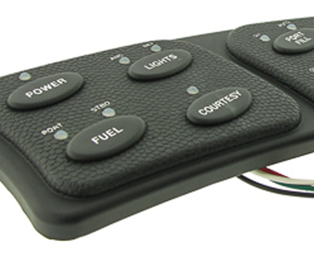
Figure 3: Molded rubber boot with general backlighting and status LEDs.
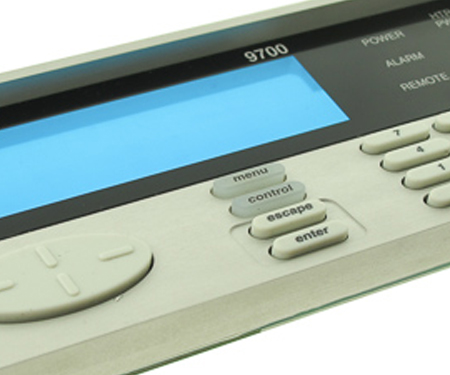
Figure 4: Molded rubber boot protruding through a bezel with translucent backlighted keytops.
Rubber boots can be molded using translucent silicone rubber. The outside visual surface is coated with opaque colors with laser etching through the opaque colors to provide backlighting and status indicators. The translucent rubber is a wonderful light diffuser for discrete LEDs for low ambient lighting as well as status indicators. Additionally, switch fields / key areas / keytops can be backlighted. This feature allows a key area to be selectively illuminated. As the TV infomercial says, "And wait!" The keytop area can also change color to indicate a function change as well as status using either bi-color LEDs or separate LEDs to backlight the keytop area.
Looking for the Best Backlighting Solution
Distilling the backlighting option pros and cons with practical decisions about cost and high performance, there are two design approaches that stand above others. The first approach for backlighted user interface is a rigid "membrane" keypad based on a printed circuit board, with tactile metal dome switches, graphic overlay and discrete LEDs for status indicators. The printed circuit board supports and connects the switches, LEDs and another electro-mechanical parts including electrical connector, current limit resistors for the LEDs and other electronic parts. The graphic overlay provides the aesthetic or visual appeal to the end user with colors, logo, status indicator windows and switch areas or keytops over the metal dome switches. An ESD and EMI shield can be added under the graphic overlay to isolate unwanted electrical signals or static discharges from causing harm. The only feature that is not satisfied with this approach is general backlighting in low ambient light environment that allows the end user to easily operate the user interface in darkened areas.
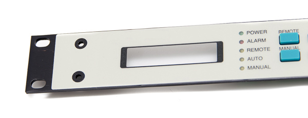
Figure 5: User Interface with graphic overlay and status LEDs.
The second approach replaces the graphic overlay with a molded silicone rubber boot. The rubber boot can be molded using translucent white rubber that makes a great diffuser for backlighting for general, low ambient light environments. The rubber boot has a secondary manufacturing operation which adds a layer of translucent white on the front surface of the rubber boot, followed by a layer of opaque color. A computer guided laser is used to "etch" through the opaque color but leaves the translucent white layer intact. General backlighting is provided with a number of LEDs distributed evenly under the rubber boot.
When these LEDs are illuminated, the LED color shows through translucent rubber and illuminates the translucent white layer. Individual LEDs can be used for status indicators where needed. The status LEDs are generally brighter as unambiguous indicators. A means of isolating the bright LEDs to light specific areas of the rubber boot must be provided. Simple and low cost techniques block unintended light leakage. Besides simple LED status indicators, another option involves either molding a translucent keytop over the metal dome switch. The keytop can be illuminated by an LED mounted next to the metal dome switch to light the keytop.
Additional LEDs of different color or bi-color LEDs can illuminate the keytop and even change its color indicating key function, use or status. This approach offers the similar cost compared to the graphic overlay approach but has a one-time tooling cost that is several thousand dollars more.
HMI Backlighting Technology - Pros & Cons
| Backlighting Technology | Pros | Cons |
|---|---|---|
| Discrete LEDs |
|
|
| E/L Lamps |
|
|
| Fiber Optic Panels |
|
|
Summary
Backlighting provides added visual features and enhances the operation of user interfaces to the end user. Choosing the backlighting requirement before proceeding with the user interface design and fabrication of assemblies prevents wasted development time and cost. Any of the backlighting techniques can be used but limitations and tooling costs must be considered as there is no "one size fits all" approach. OEM designers and user interface manufacturers must understand the interrelationship of the various components in the user interface for a successful design solution. Ignoring or changing any one component can lead to other aspects of the design being affected adversely.
Successful OEM designers or industrial designers should work early in the design concept phase to keep from being painted into a corner. Choosing the user interface manufacturer with the knowledge and backlighting experience is the first and most important step.
Not Sure What Backlighting Solution Would Be Best For Your Application?
Our team of engineers can help you to design and manufacture a custom human-machine interface with discrete LEDs, electroluminescent lamps, or fiber optics.
Request a Quote Request Design Support

